Suzuki Grand Vitara JB416 / JB420. Manual — part 89
1D-24 Engine Mechanical: For M16A Engine with VVT
Installation
CAUTION
!
After timing chain is removed, never turn
crankshaft and camshafts independently
more than such an extent (“a”, “b”) as shown
in the figure.
If turned, interference may occur between
piston and valves and valves themselves,
and parts related to piston and valves may be
damaged.
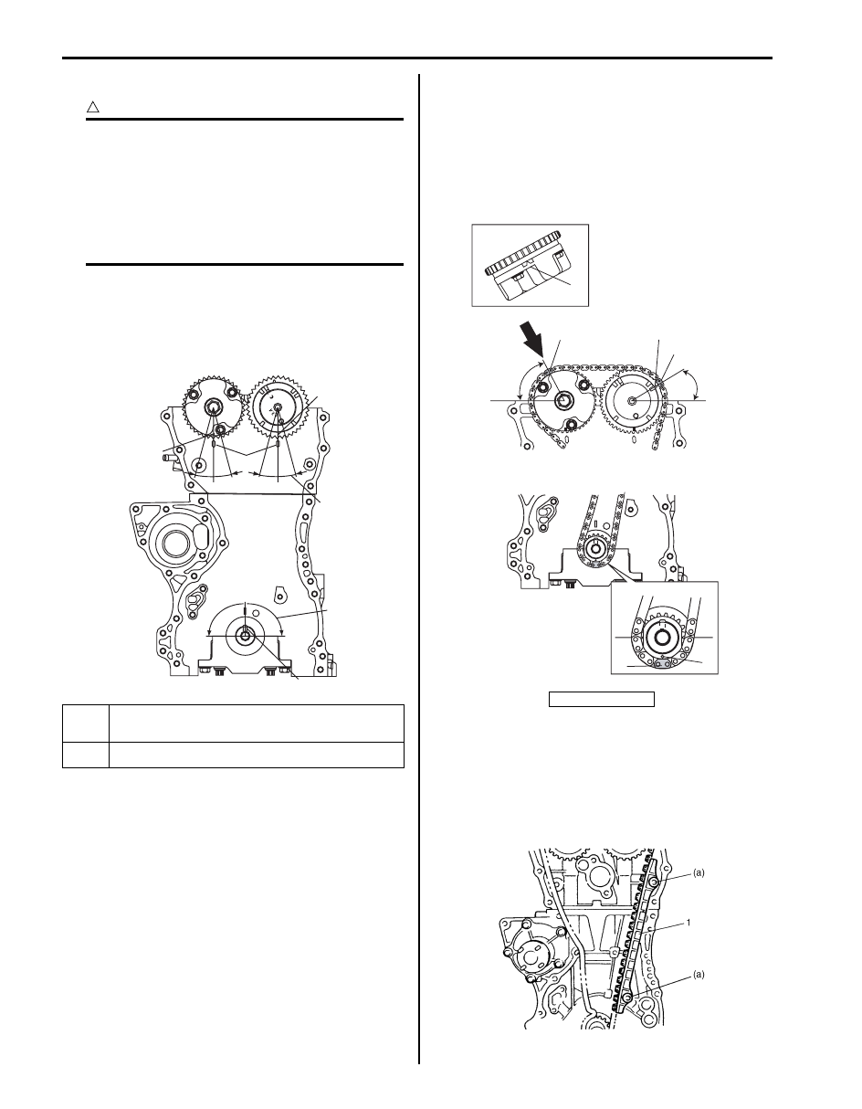
1) Check that match marks (1) on intake and exhaust
camshaft timing sprockets are in match with notches
(2) on cylinder head as shown in the figure.
2) Set key (3) and turn crankshaft to position key on
upside of crankshaft.
3) Install timing chain by aligning dark blue plate (1) of
timing chain and triangle mark (2) on camshaft
timing sprocket as shown in the figure.
4) Fit crankshaft timing sprocket to timing chain by
aligning gold plate (3) of timing chain and circle mark
(4) on crankshaft timing sprocket. Then install
crankshaft timing sprocket fitted with chain to
crankshaft.
5) Apply engine oil to sliding surface of timing chain
No.1 guide (1) and install it as shown in the figure.
Tighten guide bolts to specified torque.
Tightening torque
Timing chain No.1 guide bolt (a): 11 N·m (1.1
kgf-m, 8.0 lb-ft)
“a”: 90
°
4. Camshaft (IN and EX) allowable turning range.
By marks on camshaft timing sprocket within 15
° from notches
on cylinder head on both right and left.
“b”: 15
°
5. Crankshaft allowable turning range.
By key on crankshaft, within 90
° from top on both right and left.
“a”
“b”
“b”
“b”
“b”
“a”
1
1
2
4
3
5
I4RS0A140021-01
[A]: View A
1
1
2
2
3
4
Approx.
60˚
Approx.
30˚
A
[A]
I3RH0B140034-03
I2RH0B140062-01
Engine Mechanical: For M16A Engine with VVT 1D-25
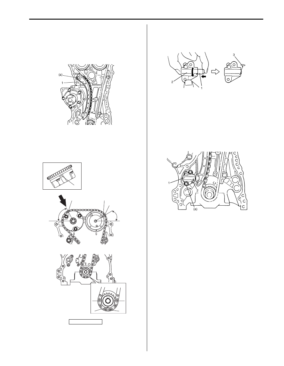
6) Apply engine oil to sliding surface of chain tensioner
(1) and install chain tensioner and spacer.
Tighten tensioner bolt to specified torque.
Tightening torque
Timing chain tensioner bolt (a): 25 N·m (2.5 kgf-
m, 18.0 lb-ft)
7) Check that match marks (1) on intake and exhaust
camshaft timing sprockets are in match with dark
blue plates (2) of timing chain and match mark (3) on
crankshaft timing sprocket is in match with gold plate
(4) of timing chain.
8) Screw in plunger (1) by turning body (2) in arrow
direction and install a retainer (3) (wire) to hold
plunger in place.
9) Install timing chain tensioner adjuster assembly (1)
with a retainer (2).
Tighten adjuster bolts to specified torque and then
remove a retainer from chain tensioner adjuster
assembly.
Tightening torque
Timing chain tensioner adjuster bolt (a): 11 N·m
(1.1 kgf-m, 8.0 lb-ft)
[A]: View A
I2RH0B140063-01
2
2
1
1
3
4
Approx.
60˚
Approx.
30˚
A
[A]
I3RH0B140035-03
I2RH0B140065-01
I2RH0B140066-01

1D-26 Engine Mechanical: For M16A Engine with VVT
10) Apply engine oil to timing chain and then turn
crankshaft clockwise by 2 revolutions and check that
match marks (1) on intake and exhaust camshaft
timing sprockets are in match with notches (2) on
cylinder head and key (3) is in match with notch (4)
on cylinder black as shown in the figure.
If each marking chain and each match mark are no
matches, adjust each sprockets and timing chain.
11) Install timing chain cover referring to “Timing Chain
Cover Removal and Installation: For M16A Engine
with VVT”.
12) Perform Steps 3) to 8) of “Installation” of “Timing
Chain Cover Removal and Installation: For M16A
Engine with VVT”.
Timing Chain and Chain Tensioner Inspection
S5JB0A1416019
Timing Chain No.1 Guide
Check shoe (1) for wear or damage.
Timing Chain Tensioner
Check shoe (1) for wear or damage.
Crankshaft Timing Sprocket
Check teeth of sprocket for wear or damage.
Timing Chain
Check timing chain for wear or damage.
Timing Chain Tensioner Adjuster
Check that tooth surface (1) are free from damage.
1
1
2
3
4
I3RH0B140036-01
I2RH0B140068-01
I2RH0B140069-01
I2RH0B140070-01
I2RH01140077-01
I2RH0B140071-01

Engine Mechanical: For M16A Engine with VVT 1D-27
Camshaft, Tappet and Shim Components
S5JB0A1416020
Camshaft, Tappet and Shim Removal and
Installation
S5JB0A1416021
CAUTION
!
• Keep working table, tools and hands clean
while overhauling.
• Use special care to handle aluminum parts
so as not to damage them.
• Do not expose removed parts to dust.
Keep them always clean.
Removal
1) Remove timing chain cover referring to “Timing
Chain Cover Removal and Installation: For M16A
Engine with VVT”.
2) Remove timing chain referring to “Timing Chain and
Chain Tensioner Removal and Installation: For M16A
Engine with VVT”.
3) With hexagonal section (1) of intake camshaft (2)
held stationary with spanner or the like, loosen
mounting bolt of intake cam timing sprocket
assembly (3) and remove it.
CAUTION
!
Never attempt to loosen mounting bolt with
intake cam timing sprocket assembly held
stationary. Failure to follow this could result
in damage to lock pin.
Do not loosen bolt “a” because intake cam
timing sprocket assembly is not serviceable.
I4RS0A140013-01
1. Intake camshaft
5. Shim
: Shim No. on it faces tappet side.
9. Upper camshaft bearing
: Install a bearing half with some holes to upper side of intake
camshaft No.1 bearing.
2. Intake camshaft sprocket assembly
6. Tappet
: 60 N
⋅m (6.0 kgf-m, 43.5 lb-ft)
3. Intake camshaft sprocket bolt
7. Camshaft housing
: 11 N
⋅m (1.1 kgf-m, 8.0 lb-ft)
4. Exhaust camshaft
8. Camshaft housing bolt
: Apply engine oil to sliding surface of each part.
3
“a”
1
2
I3RM0A140030-01
Нет комментариевНе стесняйтесь поделиться с нами вашим ценным мнением.
Текст