Suzuki Grand Vitara JB416 / JB420. Manual — part 270
6C-14 Power Assisted Steering System:
Tightening torque
Steering lower shaft bolt: 25 N·m (2.5 kgf-m, 18.5
lb-ft)
Gear case high pressure pipe union bolt: 35 N·m
(3.5 kgf-m, 25.5 lb-ft)
Gear case cylinder pipe flare nut: 25 N·m (2.5 kgf-
m, 18.0 lb-ft)
Gear case mounting bolt: 105 N·m (10.5 kgf-m, 76
lb-ft)
Gear case low pressure pipe union bolt: 40 N·m (
4.0 kgf-m, 29.0 lb-ft)
Stabilizer bar mount bracket mount bolt (a): 60
N·m (6.0 kgf-m, 43.0 lb-ft)
• After installation, be sure to fill specified P/S fluid and
bleed air. Refer to “P/S System Air Bleeding
Procedure”.
• Check toe setting. Adjust as required. Refer to “Front
Wheel Alignment Inspection and Adjustment in
Section 2B”.
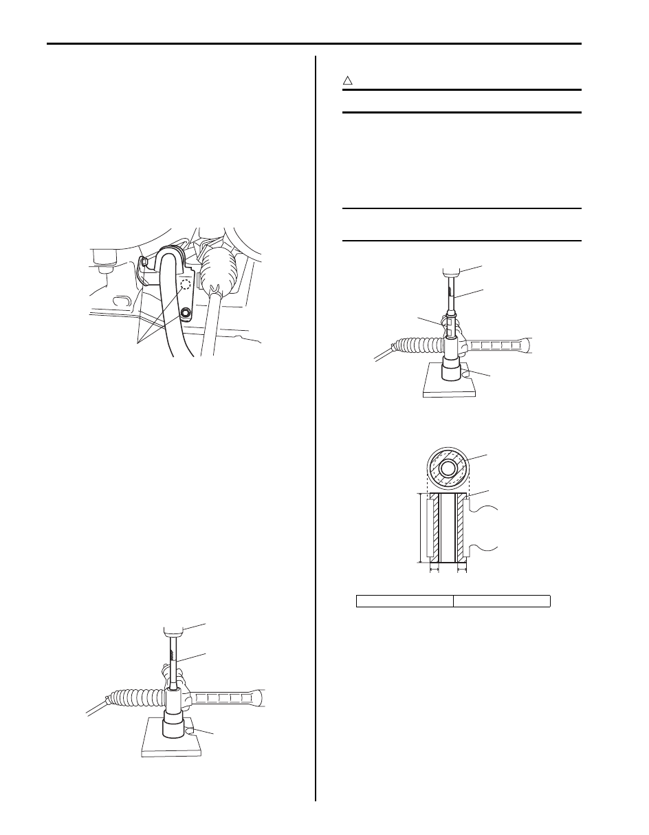
Steering Gear Case Mount Bushing Removal
and Installation
S5JB0A6306024
Removal
1) Remove P/S gear case assembly referring to “P/S
Gear Case Assembly Removal and Installation”.
2) Push out bushing using hydraulic press (1) and
special tools.
Special tool
(A): 09943–88211
(B): 09945–55410
Installation
CAUTION
!
Be sure to use new bushing.
1) Press-fit bushing (1) using special tools and press
(2).
Special tool
(A): 09913–75821
(B): 09945–55410
NOTE
Before installing bushing, apply soap water
on its circumference to facilitate installation.
2) Press-fit bushing (1) so that dimensions and in figure
become equal.
3) Install P/S gear case assembly referring to “P/S
Gear Case Assembly Removal and Installation”.
Steering Gear Case Mount Bushing Inspection
S5JB0A6306025
Inspect for looseness, cracks, deformation or damage.
Replace any defective part.
(a)
I5JB0A630021-02
(A)
1
(B)
I5JB0A630053-02
“A”: 6 mm (0.24 in.)
“B”: 80 mm (3.15 in.)
(A)
2
1
(B)
I5JB0A630055-01
1
1
“B”
“A”
“A”
I5JB0A630056-01
Power Assisted Steering System: 6C-15
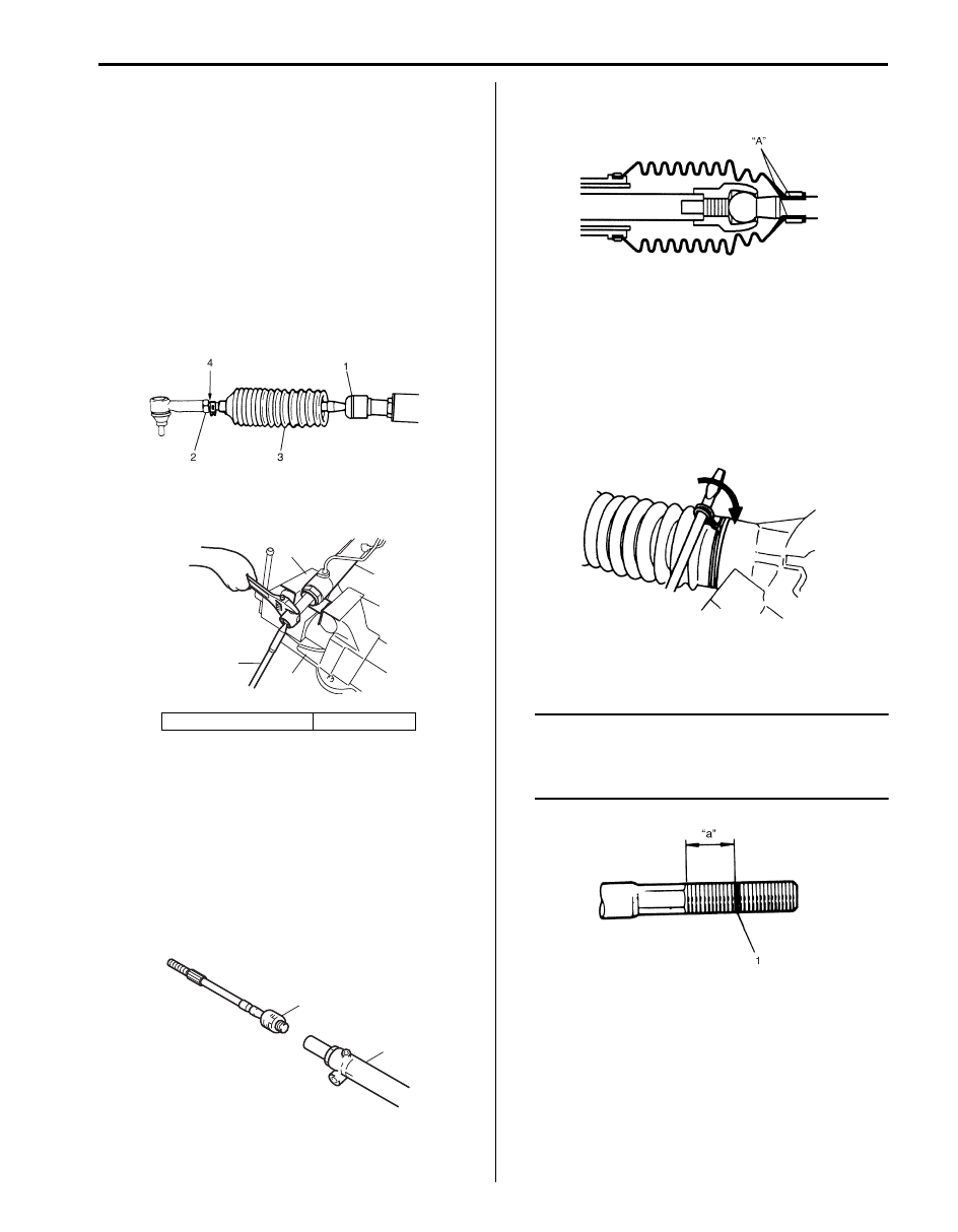
Rack Boot / Tie-Rod Removal and Installation
S5JB0A6306010
Removal
1) Remove P/S gear case assembly, referring to “P/S
Gear Case Assembly Removal and Installation”.
2) For ease of adjustment after installation, make
marking (4) of tie-rod end lock nut position of tie-rod
thread.
3) Loosen tie-rod end lock nut (2) and remove tie-rod
end.
4) Remove boot wire and clip.
5) Remove boot (3) from tie-rod (1).
6) Remove tie-rod (1) from steering gear case (2).
Installation
1) Clean threads of both tie-rod and steering gear case
(2).
2) Apply thread lock cement to thread of tie-rod ball nut
(1) and then tighten it to specified torque.
“B”: Thread lock cement 99000–32100 (Thread
Lock Cement 1305)
Tightening torque
Tie-rod ball nut (a): 90 N·m (9.0 kgf-m, 65.0 lb-ft)
3) Apply grease to boot inside “A” indicated in the
figure.
4) Position boot properly in grooves of gear case and
tie-rod. Check to ensure that boot is free from twist
and dent.
5) Clamp boot with clip and wire. Wire should be new
and should go around the boot twice.
Pull its both ends together by screwdriver or such
and make sure that the wire won’t be crossed. Then
twist the ends several times, the twisted ends should
be bent in the circumferential direction.
6) Install tie-rod end lock nut and tie-rod end to tie-rod.
Position lock nut to marking (1) made in removal.
NOTE
When tie-rod was replaced, measure length
“a” on removed tie-rod and use it on new
replacement tie-rod so as to position lock nut
properly.
7) Install steering gear case. Refer to “P/S Gear Case
Assembly Removal and Installation”.
3. Aluminium plate
4. Vise
I5JB0A630054-01
3
1
4
2
3
I5JB0A630022-01
2
1, (a), “B”
I5JB0A630023-03
IYSQ01630030-01
IYSQ01630035-01
I5JB0A630058-01
6C-16 Power Assisted Steering System:
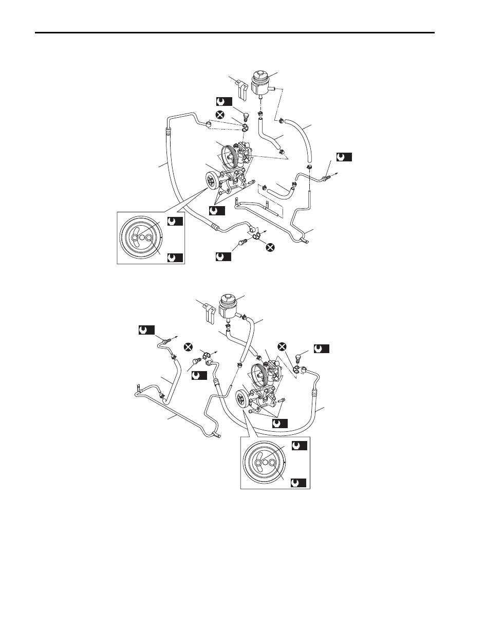
P/S Hose / Pipe Components
S5JB0A6306011
[A]
[B]
7
1
6
4
2
11
9
3
5
6
6
(b)
13
13
13
1
10
(a)
15
(a)
14
(a)
(c)
10
(c)
12
(c)
12
(c)
13
16
16
7
5
2
16
16
3
6
4
9
6
6
11
(a)
15
(a)
14
(a)
(b)
I5JB0A630024-04
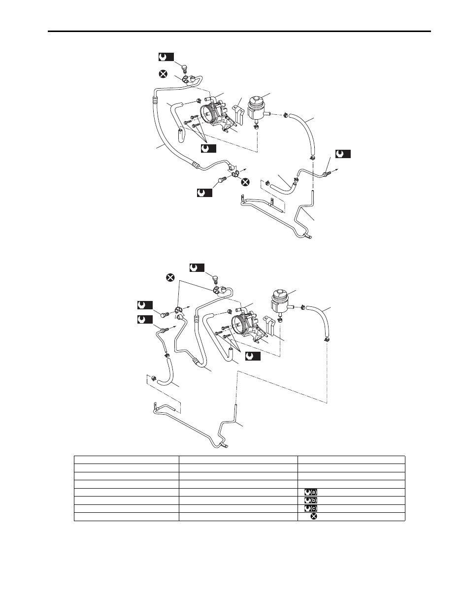
Power Assisted Steering System: 6C-17
[C]
[D]
9
(b)
13
5
2
16
16
1
4
3
6
7
11
(a)
(c)
13
6
6
12
(c)
9
10
(b)
13
16
16
12
6
(c)
10
(c)
6
4
5
11
(a)
2
7
1
3
6
I5JB0A630025-05
[A]: M16 engine LH steering vehicle
5. Suction hose
13. Washer
[B]: M16 engine RH steering vehicle
6. Low pressure return hose
14. P/S belt tension pulley bolt
[C]: J20 engine LH steering vehicle
7. P/S fluid reservoir bracket
15. P/S belt tension pulley nut
[D]: J20 engine RH steering vehicle
8. To P/S gear case
16. To P/S gear case assembly
1. P/S pump assembly
9. P/S pump union bolt
: 25 N
⋅m (2.5 kgf-m, 18.0 lb-ft)
2. Bracket
10. P/S gear case high pressure union bolt
: 60 N
⋅m (6.0 kgf-m, 43.5 lb-ft)
3. P/S fluid reservoir
11. P/S pump mounting bolt
: 35 N
⋅m (3.5 kgf-m, 25.5 lb-ft)
4. High pressure hose and pipe
12. P/S gear case low pressure flare nut
: Do not reuse.
Нет комментариевНе стесняйтесь поделиться с нами вашим ценным мнением.
Текст