Suzuki Grand Vitara JB416 / JB420. Manual — part 413

10B-18 Body Electrical Control System:
DTC Detecting Condition and Possible Cause
Flow Test Description
Step 1: Check air bag communication circuit.
Step 2: Check air bag communication circuit.
Step 3: Check air bag communication circuit.
DTC Troubleshooting
DTC detecting condition
Possible cause
After ignition switch is turned on, abnormal signal is fed
from SDM to BCM.
• Air bag communication circuit open or short
• SDM malfunction
• BCM malfunction
Step
Action
Yes
No
1
Check air bag communication circuit
1) Turn ignition switch to OFF position.
2) Disconnect connector from SDM referring to “SDM
Removal and Installation in Section 8B”.
3) Disconnect connector from BCM.
4) Turn ignition switch to ON position.
5) Measure voltage between “G47-22” or “G46-15” terminal
of SDM connector and vehicle body ground.
Is voltage 0 V?
Go to Step 2.
Short to power supply in
air bag communication
circuit.
2
Check air bag communication circuit
1) Turn ignition switch to OFF position.
2) Connect connectors to BCM.
3) Turn ignition switch to ON position.
4) Measure voltage between “G30-19” terminal of BCM
connector and vehicle body ground.
Is voltage 4 – 6 V?
Go to Step 3.
Short to ground in air
bag communication
circuit. If OK, substitute
a known-good BCM and
recheck.
3
Check air bag communication circuit
1) Measure voltage between “G47-22” or “G46-15” terminal
of SDM connector and vehicle body ground.
Is voltage 4 – 6 V?
Substitute a known-
good SDM and recheck.
Open or high resistance
in air bag
communication circuit.
Body Electrical Control System: 10B-19
DTC B1157 (No. 1157): Air Bag Deployment Signal Input
S5JB0AA204011
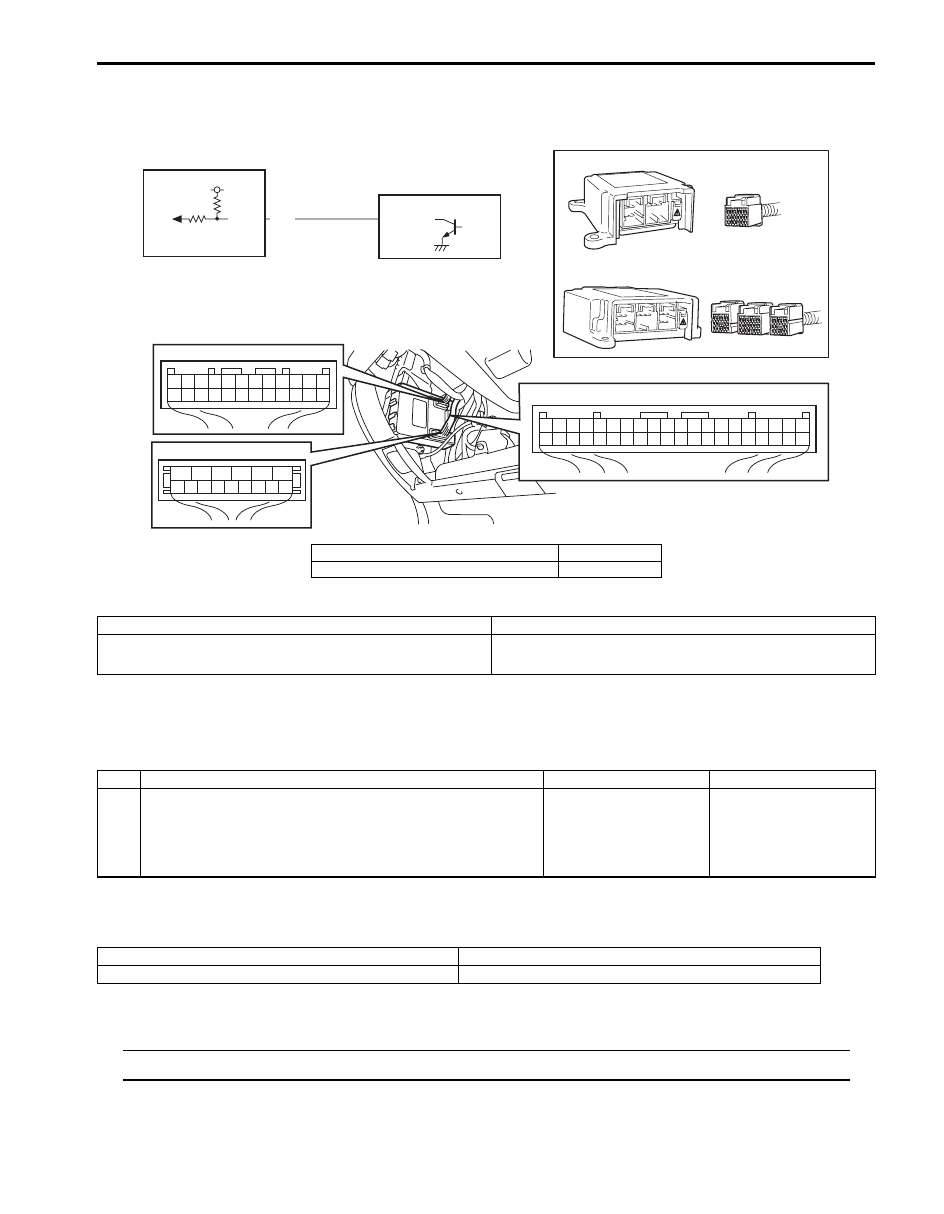
Wiring Diagram
DTC Detecting Condition and Possible cause
Flow Test Description
Step 1: Check DTC for SDM.
DTC troubleshooting
DTC B1170 (No. 1170): EEPROM access error
S5JB0AA204012
DTC Detecting Condition and Possible Cause
DTC Troubleshooting
NOTE
Before performing steps below, be sure to perform “Body Electrical Control System Check”.
1) Ignition switch OFF.
2) Replace BCM.
3) Repeat BCM Check Flow Table.
7
8
9
10
11
12
13
14
15
6
5
4
3
2
1
G32
24
1
2
3
4
5
6
7
8
9
10
11
12
13
14
15
16
17
18
19
20
21
22
23
G30
1
2
3
4
5
6
7
8
9
10
11
12
13
14
15
16
17
18
19
20
21
22
23
24
25
26
27
28
29
30
31
32
33
34
35
36
37
38
39
40
G31
YEL
5V
G30-19
[A]: G47-22
[B]: G46-15
[A]
[B]
2
1
G47
G46
I5JB0AA20009-02
[A]: Vehicle not equipped with side-air bag
1. SDM
[B]: Vehicle equipped with side-air bag
2. BCM
DTC detecting condition
Possible cause
Air bag deployment signal is fed from SDM to BCM.
• Air bag component parts
• BCM malfunction
Step
Action
Yes
No
1
Check DTC for SDM
1) Check DTC stored in SDM referring to “DTC Check in
Is DTC B1021 detected?
Go to “DTC B1021: Air
Bag Module Deployed
in Section 8B”.
Substitute a known-
good BCM and recheck.
DTC detecting condition
Possible cause
Data write error or check sum error.
BCM malfunction
10B-20 Body Electrical Control System:
DTC U1073 (No. 1073): Control Module Communication Bus Off
S5JB0AA204014
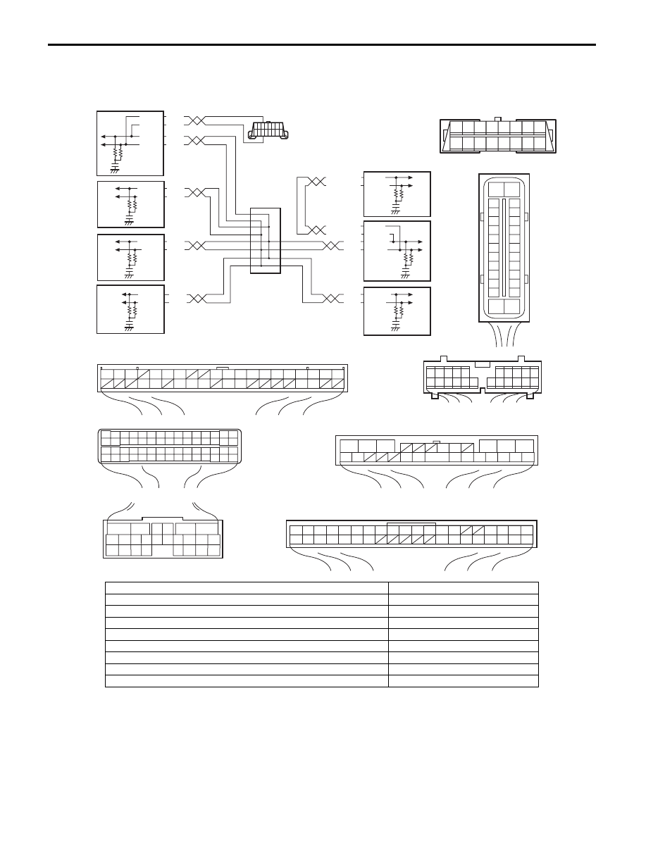
Wiring Diagram
WHT
RED
WHT
RED
G44-18
G44-19
G44
[A]
[B]
[C]
[H]
[G]
1
2
3
4
5
6
7
8
9
10
11
14
15
16
36
34 33 32
30 29
24 23
37
18
19
20
G28-8
G28-10
WHT/BLU
WHT/BLU
WHT/RED
WHT/RED E23-4
E23-19
WHT
RED E03-12
E03-10
E03-6
E03-8
WHT
RED
E92-17
E92-7
WHT
RED
E91-22
E91-23
WHT
RED
RED
G31-1
G31-3
G31-4
6
5
16 15 14 13 12 11
4 3
24 23
21
22
10 9
8
7
2
1
19
20
18 17
E92
2 1
E23
3
4
18
19
5
6
7
10
11
17
20
47 46
49
50
51
21
22
52
16
25
9
24
14
29
55
57
5453
59
60
58
26
27
28
15
30
56
48
32 31
34
35
36
37
40
42
3938
44
45
43
41
33
12
13
23
8
1
2
3
4
5
6
7
8
9
10
11
17
1615141312
2221201918
G28
[F]
G31
E91
1
2
3
4
7
8
9
10
11
14
15
16
36
34
35
24 23
21
22
28 27
25
26
37
39 38
40
18 17
13 12
19
20
1
2
3
10
11
12
16
17
18
15 14 13
19
20
21
25
26
5
6
[E]
[D]
E03
15
16
17
18
19
20
21
22
23
24
25
2
3
4
5
6
7
8
9
10
11
12
1
13
14
26
8 7 6 5 4 3 2 1
9
10
11
12
13
14
15
16
G31-2
WHT
1
2
3
4
9
5
6
7
8
I5JB0AA50017-03
[A]: Keyless start control module connector (viewed from harness side)
1. Keyless start control module
[B]: ECM connector (viewed from harness side)
2. TCM (A/T model)
[C]: TCM connector (viewed from harness side)
3. 4WD control module (if equipped)
[D]: DLC (viewed from harness side)
4. BCM
[E]: ABS hydraulic unit/control module connector (viewed from harness side)
5. DLC
[F]: Combination meter connector (viewed from harness side)
6. ECM
[G]: 4WD control module connector (viewed from harness side)
7. ABS hydraulic unit/control module
[H]: BCM connector (viewed from harness side)
8. Combination meter
9. Junction connector

Body Electrical Control System: 10B-21
DTC Detecting Condition and Trouble Area
DTC Confirmation Procedure
1) Connect scan tool to DLC with ignition switch turned OFF.
2) Turn ON ignition switch and clear DTC by using scan tool.
3) Start engine and run it for 1 min. or more.
4) Check DTC and pending DTC.
Troubleshooting
DTC detecting condition
Trouble area
Transmission error that is inconsistent between transmission data
and transmission monitor (CAN bus monitor) data is detected more
than 7 times continuously.
(1 driving detection logic)
• CAN circuit
• Combination meter
• BCM
• 4WD control module (if equipped)
• ABS hydraulic unit/control module
• TCM (A/T model)
• Keyless start control module (if equipped)
• ECM
Step
Action
Yes
No
1
Check each control unit connectors
1) Check connection of connectors of all control modules
communicating by means of CAN and reconnect
securely.
2) Recheck DTC and reconnect securely.
Is DTC U1073 detected?
Go to Step 2.
Intermittent trouble.
Check for intermittent
referring to “Intermittent
and Poor Connection
Inspection in Section
00”.
2
CAN communication circuit check
1) Turn ignition switch to OFF position.
2) Disconnect connectors of all control modules
communicating by means of CAN.
3) Check CAN communication circuit between control
modules for open, short and high resistance.
Is each CAN communication circuit in good condition?
Go to Step 3.
Repair circuit.
Нет комментариевНе стесняйтесь поделиться с нами вашим ценным мнением.
Текст