Suzuki Grand Vitara JB416 / JB420. Manual — part 411

10B-10 Body Electrical Control System:
Scan Tool Data
S5JB0AA204003
Scan Tool Data Definitions
Vehicle Speed (km/h, mph): This parameter indicates the vehicle speed computed by ECM.
Outside air Temp (
°C, °F): It is detected by outside air temperature sensor.
Battery Voltage (V): This parameter indicates battery positive voltage inputted to BCM.
Coolant Temp (Engine coolant temperature) (
°C, °F): This parameter indicates the engine coolant temperature
computed by ECM.
Engine Speed (RPM): This parameter indicates the engine speed computed by ECM.
Fuel Consumption (km/l): This parameter indicates the fuel consumption computed by ECM.
Key Reminder Sw (Key reminder switch) (Pulled / Key in): This parameter indicates the state of the key reminder
switch.
Door key Sw (Door key cylinder switch) (Lock / Neutral / Unlock): This parameter indicates the state of the door
key cylinder switch.
Door lock Sw (Manual door lock switch) (Lock / Neutral / Unlock): This parameter indicates the state of the
manual door lock switch.
Driv Door Sw (Driver side door switch) (Open / Close): This parameter indicates the state of the driver side door
switch.
Scan tool Data
Condition
Normal condition /
reference value
Vehicle Speed
At stop with ignition switch turned ON
0 km/h
Outside air Temp
Reference value is relative to outside air temperature
–40
°C – 70 °C
(–40
°F – 158 °F)
Battery Voltage
At specified idle speed after warming up
10 – 14 V
Coolant Temp
At specified idle speed after warming up
80
°C – 100 °C
(176
°F – 212 °F)
Engine Speed
Engine idling with no load applied after warming up
Desired idle speed
± 50 rpm
Fuel Consumption
At specified idle speed after warming up
0.0 km/l
Key Reminder Sw
Ignition key inserted in ignition key cylinder
Key in
Ignition key pulled out from ignition key cylinder
Pulled
Door key Sw
Key cylinder switch of driver side door at lock position
LOCK
Key cylinder switch of driver side door not turned
Neutral
Key cylinder switch of driver side door at unlock position
Unlock
Door Lock Sw
Lock side of manual door lock switch pressed
LOCK
Manual door lock switch not pressed
Neutral
Unlock side of manual door lock switch pressed
Unlock
Driv Door Sw
Driver side door open
Open
Driver side door closed
Close
Pass Door Sw
Doors other than driver side door open
Open
Doors other than driver side door closed
Close
Brake Fluid Level
Brake fluid level at MIN level or higher
Normal
Brake fluid level lower than MIN level
Low
Parking Brake Sw
Parking brake lever pulled
ON
Parking brake lever released
OFF
Rear Defogger Sw
Rear end door window defogger switch turned ON with engine
running
ON
Rear end door window defogger switch turned OFF with engine
running
OFF
Tail Light Sw
Lighting switch at HEAD or CLEARANCE position
ON
Lighting switch at OFF position
OFF
Driv Seat belt Sw
Driver side seat belt fastened
Fasten
Driver side seat belt unfastened
Unfasten
Charge Lamp
Engine at stop with ignition switch turned ON
ON
Engine running
OFF
Oil pressure switch
Engine at stop with ignition switch turned ON
ON
Engine running
OFF
A/C Switch
A/C and ignition switch turned ON
ON
A/C switch turned OFF
OFF
Body Electrical Control System: 10B-11
Pass Door Sw (Other than driver side door switch) (Open / Close): This parameter indicates the state of the door
switches other than driver side door switch.
Brake Fluid Level (Low / Normal): Low: Brake fluid level is lower than specified level.
Normal: Brake fluid level is higher than MIN level.
Parking Brake Sw (Parking brake switch) (ON / OFF): ON: Parking brake lever is pulled up.
OFF: Parking lever is released
Rear Defogger Sw (Rear end door window defogger switch) (ON / OFF): This parameter indicates the state of
the rear end door window defogger switch.
Tail Light Sw (Lighting switch) (ON / OFF): This parameter indicates the state of the lighting switch.
Driv Seat belt Sw (Driver seat belt switch) (Fasten / Unfasten): This parameter indicates the state of the driver
side seat belt buckle switch.
Charge lamp (ON / OFF): This parameter indicates the state of the charge system monitor switch.
Oil pressure switch (ON / OFF): This parameter indicates the state of the oil pressure switch.
A/C Switch (ON / OFF): This parameter indicates the state of the air conditioning switch.
Diagnosis Using Output Test Function of SUZUKI Scan Tool
SUZUKI scan tool has the output test function which can force operation of following actuators and relays of the
system controlled by BCM. When a malfunction is found in the system controlled by BCM, execute the output test
which enables easy judgment whether the malfunction is on the input side or output side of BCM. For detailed
information on operation of SUZUKI scan tool, refer to “SUZUKI Scan Tool Operator’s Manual”.
DTC Table
S5JB0AA204004
Output Test Item
Controlled Parts
Hazard Warning Light
Turn signal and hazard warning relay
Interior (Dome) Light
Interior (Dome) light (when interior light switch is at DOOR position)
Parking/Tail Light
Tail light relay
Front Fog Light
Front fog light relay (when lighting switch is at CLEARANCE position)
Rear defogger
Rear defogger and mirror heater relays
D.R.L.
Headlight low beam relay
Auto on headlight
Headlight low beam and tail light relays
Door
Each door lock actuator
Warning buzzer
Warning buzzer (in BCM)
Rear wiper
Rear wiper relay
Alarm indicator
Theft deterrent light (in HVAC control module)
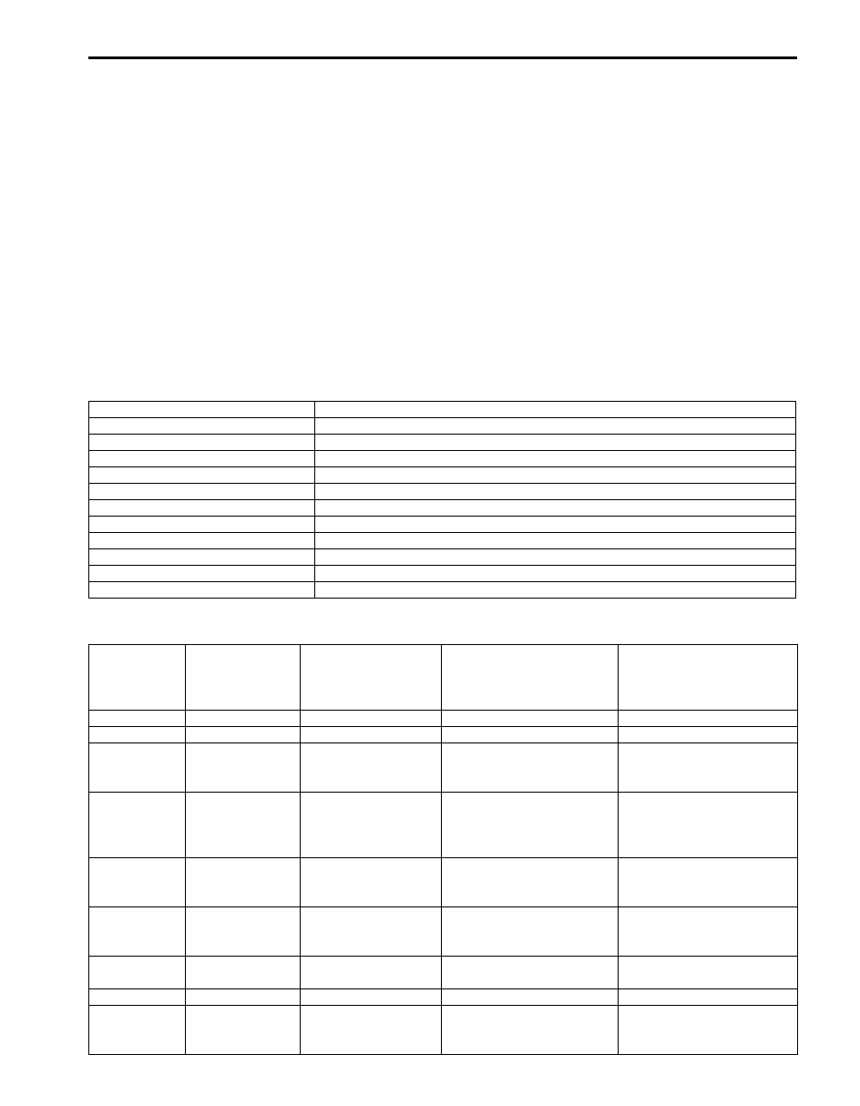
DTC
(displayed on
SUZUKI scan
tool)
DTC (indicated
by theft
deterrent light)
DTC (displayed on
odometer in
combination meter)
Detected item
Detecting condition
NO DTC
0000
0000
—
No DTC detected
B1133
1133
b1133
Battery voltage too high
Battery voltage too high
B1141
1141
b1141
Outside air temperature
(ambient temperature)
sensor circuit open
Sensor output voltage too
high
B1142
1142
b1142
Outside air temperature
(ambient temperature)
sensor circuit short to
ground
Sensor output voltage too
low
B1143
1143
b1143
Outside air temperature
(ambient temperature)
sensor malfunction
Sensor output voltage out of
specification
B1150
1150
b1150
Air bag communication
circuit malfunction
Air bag communication
circuit open or short to
ground
B1157
1157
b1157
Air bag deployment signal
input
Air bag deployment signal
inputted
B1170
1170
b1170
EEPROM access error
Memory error
U1073
1073
U1073
Control module
communication bus off
Transmitting and receiving
error of BCM for specified
time continuously
10B-12 Body Electrical Control System:
DTC Check
S5JB0AA204005
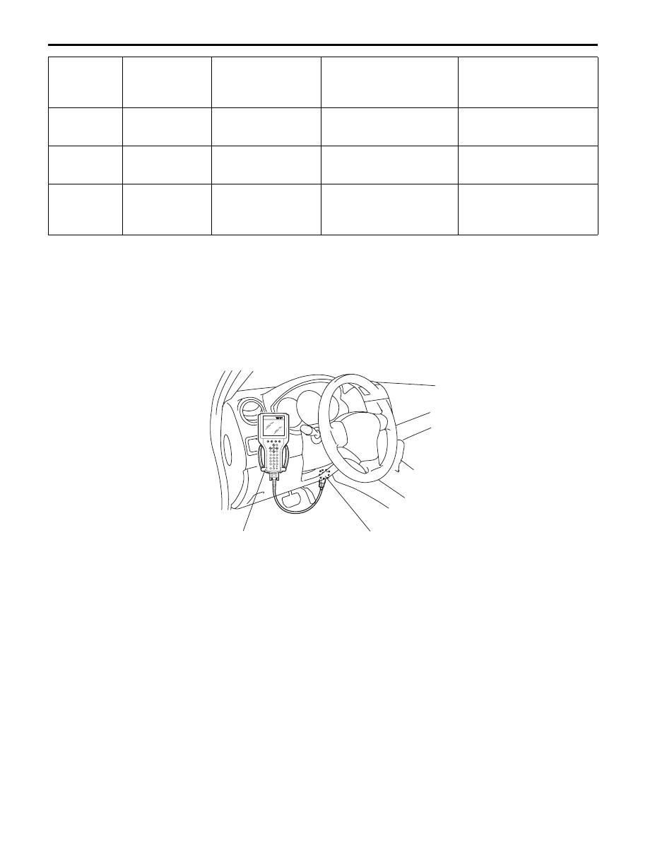
Using SUZUKI Scan Tool
1) Prepare SUZUKI scan tool.
2) With ignition switch turned OFF, connect it to data link connector (DLC) located on underside of instrument panel
of driver’s side.
Special tool
(A): SUZUKI scan tool
3) Turn ignition switch ON.
4) Read DTC according to instructions displayed on SUZUKI scan tool and print it or write it down.
Refer to SUZUKI scan tool operator’s manual for further details.
If communication between SUZUKI scan tool and BCM is not possible, check if SUZUKI scan tool is
communicable by connecting it to BCM in another vehicle. If communication is possible in this case, SUZUKI scan
tool is in good condition. Then check data link connector and serial data line (circuit) in the vehicle with which
communication was not possible.
5) After completing the check, turn ignition switch off and disconnect SUZUKI scan tool from data link connector.
Without Using SUZUKI Scan Tool
1) Turn ignition switch to OFF position.
2) Perform following Steps a) to d) within 10 seconds after ignition switch is turned ON and engine stops.
a) Turn lighting switch to “CLEARANCE” position.
b) Turn lighting switch to “OFF” position.
c) Repeat Steps a) and b) 2 times.
d) Press and release driver side door switch 3 times.
U1100
1100
U1100
Lost communication with
ECM
Receiving error of BCM from
ECM for specified time
continuously
U1101
1101
U1101
Lost communication with
TCM
Receiving error of BCM from
TCM for specified time
continuously
U1144
1144
U1144
Lost communication with
key free control unit
Receiving error of BCM from
keyless start control module
for specified time
continuously
DTC
(displayed on
SUZUKI scan
tool)
DTC (indicated
by theft
deterrent light)
DTC (displayed on
odometer in
combination meter)
Detected item
Detecting condition
1
(A)
I5JB0AA20005-02
Body Electrical Control System: 10B-13
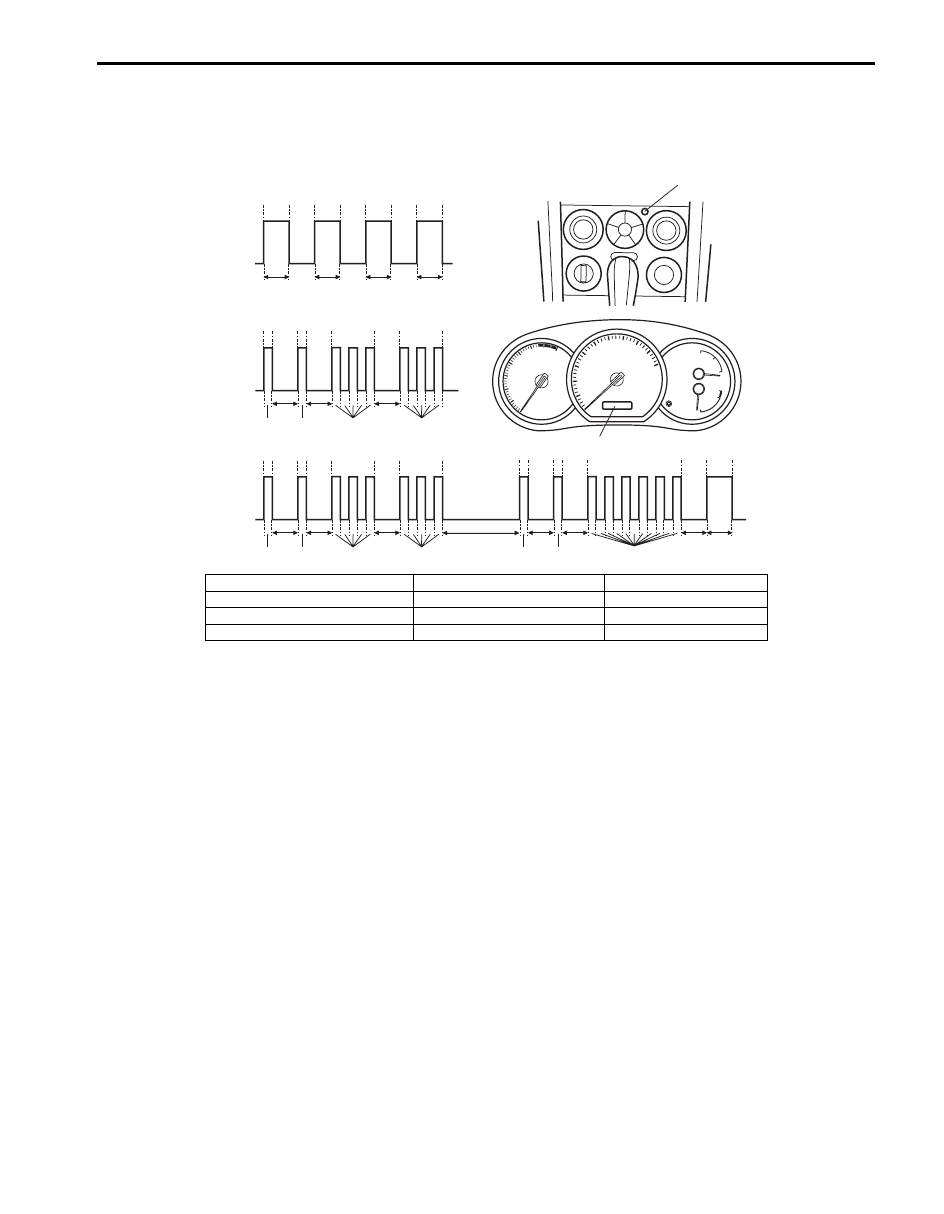
3) Check DTC displayed on odometer of combination meter or read flashing pattern of theft deterrent light which
represents DTC as shown in the following example and write it down.
When more than 2 DTCs are stored in memory, flashing for each DTC starts with the smallest DTC number in
increasing order. Also, DTC is indicated repeatedly until the ignition switch is turned OFF.
4) After completing the check, turn ignition switch to OFF position.
DTC Clearance
S5JB0AA204006
After repair or replace of malfunction part(s), clear all DTCs by performing the following procedure.
Using SUZUKI Scan Tool
1) Connect SUZUKI scan tool to data link connector in the same manner as when making this connection for DTC
check.
2) Turn ignition switch ON and engine stops.
3) Erase DTC according to instructions displayed on scan tool. Refer to scan tool operator’s manual for further
details.
4) After completing the clearance, turn ignition switch off and disconnect scan tool from data link connector.
Without Using SUZUKI Scan Tool
1) Turn ignition switch to OFF position.
2) Perform following Steps a) to d) within 10 seconds after ignition switch is turned ON and engine stops.
a) Turn lighting switch to “CLEARANCE” position.
b) Turn lighting switch to “OFF” position.
c) Repeat Steps a) and b) 3 times.
d) Press and release driver side door switch 4 times.
3) After completing above Steps, confirm that no malfunction DTC is detected.
B
A
[B]
[A]
[C]
B
A
B
A
3
1
1
3
3
1
1
3
T2
T1
T1
T1
T1
T2
T2
T2
T1
T1
T1
T1
T2
T2
0
T2
0
T2
0
T2
0
T2
1
1
6
0
T1
T1
T1
T2
T3
T2
T2
T2
1
2
I5JB0AA20011-01
[A]: No DTC (No. 0000)
B: Indicator lamp turned OFF
1. Theft deterrent light
[B]: DTC B1133 (No. 1133)
T1: 0.3 seconds
2. Odometer
[C]: When 2 DTCs are detected
T2: 1.0 seconds
A: Indicator lamp turned ON
T3: 3.0 seconds
Нет комментариевНе стесняйтесь поделиться с нами вашим ценным мнением.
Текст