Suzuki Grand Vitara JB416 / JB420. Manual — part 191
3C-78 Transfer: Non-Shift Type (Transfer without Shift Actuator)
Repair Instructions
Transfer Oil Change
S5JB0A3326002
Refer to “Transfer Oil Change: Motor-Shift Type (Transfer with Shift Actuator)”.
The point which is different from the motor-shift type (transfer with shift actuator) is described.
Transfer oil capacity (Non-Shift Type)
Reference: 1.6 liters (3.4/2.8 US/lmp.pt)
Transfer Oil Level Check
S5JB0A3326003
Refer to “Transfer Oil Level Check: Motor-Shift Type (Transfer with Shift Actuator)”.
Transfer Oil Seal Removal and Installation
S5JB0A3326004
Refer to “Transfer Oil Seal Removal and Installation: Motor-Shift Type (Transfer with Shift Actuator)”.
Transfer Assembly Dismounting and Remounting
S5JB0A3326005
Refer to “Transfer Assembly Dismounting and Remounting: Motor-Shift Type (Transfer with Shift Actuator)”.

Transfer: Non-Shift Type (Transfer without Shift Actuator) 3C-79
Transfer Assembly Components
S5JB0A3326006
37
36
9
38
(c)
32
(a)
25
20
(a)
(a)
40
(a)
27
(b)
(a)
A
OIL
28
29
31
33
1217G
30
26
10
10
19
9
OIL
9
OIL
23
1217G
24
1217G
22
21
35
A
9
OIL
9
OIL
16
OIL
18
17
15
14
13
12
11
9
OIL
5
4
6
2
(a)
2
(a)
34
(a)
3
7
8
39
1217G
1
A
OIL
41
(a)
1322
(a)
I5JB0A331084-06
3C-80 Transfer: Non-Shift Type (Transfer without Shift Actuator)
Transfer Assembly Disassembly and
Reassembly
S5JB0A3326007
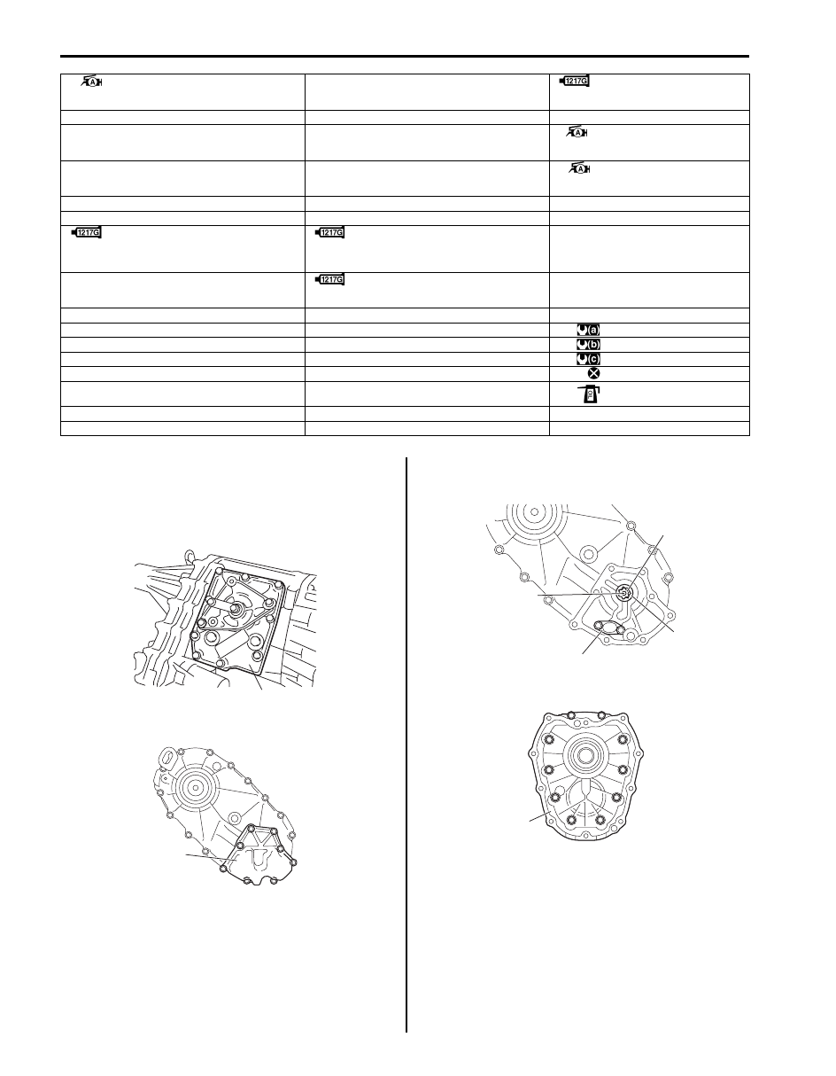
Disassembly
1) Remove differential lock shift lever case (1).
2) Remove oil pump cover (1).
3) Remove oil pump inner rotor (1), outer rotor (2), oil
strainer (4) and drive pin (3).
4) Remove front case (1).
1. Front oil seal No.1
: Apply grease 99000-25010 to oil seal lip.
17. Differential lock clutch sleeve
33. Oil drain plug
: Apply sealant 99000-31260 to
plug thread.
2. Front case bolt
18. Front drive sprocket bush
34. Transfer to transmission bolt
3. Front case
19. Front drive sprocket
35. Front oil seal No.2
: Apply grease 99000-25010 to
oil seal lip.
4. Knock pin
20. Rear output shaft assembly
36. Rear oil seal
: Apply grease 99000-25010 to
oil seal lip.
5. Oil pipe
21. Front output shaft assembly
37. Damper
6. Input gear assembly
22. Drive chain
38. Damper bolt
7. Center case
: Apply sealant 99000-31260 to mating
surface of front case, differential lock shift
lever case and center case.
23. Rear case
: Apply sealant 99000-31260 to mating
surface of transfer rear case, oil pump
cover and transfer center case.
39. Shift case
8. Differential lock shift lever case
24. Oil level / filler plug
: Apply sealant 99000-31260 to plug
thread.
40. Shift lever case bolt
9. Needle bearing
25. Rear case bolt
41. O-ring
10. Snap ring
26. Oil strainer
: 23 N
⋅m (2.3 kgf-m, 17.0 lb-ft)
11. Washer
27. Oil strainer bolt
: 10 N
⋅m (1.0 kgf-m, 7.5 lb-ft)
12. Shim
28. Oil pump outer rotor
: 50 N
⋅m (5.0 kgf-m, 36.5 lb-ft)
13. Reduction shift sleeve
29. Oil pump inner rotor
: Do not reuse.
14. Center differential assembly
30. Oil pump drive pin
: Apply transfer oil.
15. Front drive shaft
31. Oil pump cover
16. Thrust bearing
32. Oil pump cover bolt
1
I5JB0A331085-01
1
I5JB0A331086-01
1
2
4
3
I5JB0A331013-01
1
I5JB0A331014-01

Transfer: Non-Shift Type (Transfer without Shift Actuator) 3C-81
5) Remove rear case bolts (1), and then separate
center case (2) using special tool.
Special tool
(A): 09912–34510
6) Remove knock pin (1) and oil pipe (2) from center
case (4) and remove front oil seal No.1 (3) using flat
end rod or the like, if necessary.
7) Remove needle bearing (1) from center case (2)
using special tool, if necessary.
Special tool
(A): 09913–76010
8) Remove needle bearing (1), snap ring (2), washer
(3) and shim(s) (4) from rear output shaft (5).
9) Remove reduction shift sleeve (1) and center
differential (3) from rear output shaft (2).
10) Remove needle bearings (1), front drive shaft (2)
and thrust needle bearing (4) from rear output shaft
(3).
11) Remove differential lock clutch sleeve (1) from rear
output shaft (2).
1
I5JB0A331087-01
2
(A)
I5JB0A331016-02
1
2
3
4
I5JB0A331017-01
(A)
1
2
I5JB0A331088-01
1
2
3
4
5
I5JB0A331089-01
1
3
2
I5JB0A331090-02
1
1
2
3
4
I5JB0A331041-02
1
2
I5JB0A331022-01
Нет комментариевНе стесняйтесь поделиться с нами вашим ценным мнением.
Текст