Suzuki Grand Vitara JB416 / JB420. Manual — part 36

1A-93 Engine General Information and Diagnosis:
DTC Confirmation Procedure
WARNING
!
• When performing a road test, select a place where there is no traffic or possibility of a traffic
accident and be very careful during testing to avoid occurrence of an accident.
• Road test should be carried out by 2 persons, a driver and tester, on a level road.
NOTE
Check to make sure that following conditions are satisfied when using this “DTC Confirmation
Procedure”.
• Intake air temperature at engine start: –10
°C (14 °F) to 80 °C (176 °F)
• Intake air temperature: –10
°C (14 °F) to 70 °C (158 °F)
• Altitude (barometric pressure): 2400 m, 8000 ft or less (560 mmHg, 75 kPa or more)
1) With ignition switch turned OFF, connect scan tool.
2) Turn ON ignition switch, clear DTC.
3) Start engine.
4) Drive vehicle at 40 mph (60 km/h) or higher for 20 min. or more.
5) Stop vehicle.
6) Check DTC and pending DTC.
DTC Troubleshooting
NOTE
Before this trouble shooting is performed, read the precautions for DTC troubleshooting referring to
“Precautions For DTC Troubleshooting”.
Step
Action
Yes
No
1
Was “Engine and Emission Control System Check”
performed?
Go to Step 2.
Go to “Engine and
Emission Control
System Check”.
2
DTC check
1) With ignition switch turned OFF, install scan tool to DLC.
2) Turn ON ignition switch and check DTC with scan tool.
Is DTC P0118 displayed?
Go to “DTC P0118:
Engine Coolant
Temperature Circuit
High”.
Go to Step 3.
3
Engine coolant temp. check
1) Turn ON ignition switch and check engine coolant temp.
displayed on scan tool.
2) Warm up engine to normal operating temp. and check
engine coolant temp. displayed on scan tool.
Does engine coolant temp. vary more than 1
°
C (1
°
F) and
rise higher than 70
°
C (158
°
F)?
Intermittent trouble.
Check for intermittent
referring to “Intermittent
and Poor Connection
Inspection in Section
00”.
Go to Step 4.
4
Thermostat check
Is there a symptom due to thermostat remaining open (it
takes a long time before vehicle heater becomes effective or
before engine is warmed to normal operating temp., etc.)?
Check thermostat
referring to “Thermostat
Inspection in Section
1F”.
Go to Step 5.
Engine General Information and Diagnosis: 1A-94
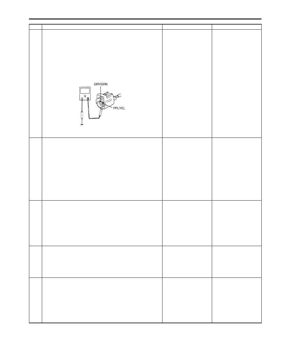
5
Wire harness check
1) Disconnect ECT sensor connector with ignition switch
turned OFF.
2) Check for proper connection to ECT sensor connector at
“PPL/YEL” and “GRY/GRN” wire terminals.
3) If OK, then with ignition switch ON, measure voltage
between “PPL/YEL” wire terminal of ECT sensor
connector and vehicle body ground.
Is voltage about 4 – 6 V?
Go to Step 9.
Go to Step 6.
6
ECM voltage check
1) Turn OFF ignition switch.
2) Remove ECM from its bracket with ECM connectors
connected.
3) Check for proper connection of ECM connector at “C37-
24” terminal.
4) If OK, then turn ON ignition switch, measure voltage
between “C37-24” terminal of ECM connector and
vehicle body ground.
Is voltage about 4 – 6 V?
“PPL/YEL” wire is open
circuit.
If wire and connection
are OK, go to Step 7.
Go to Step 7.
7
Wire circuit check
1) Disconnect connectors from ECM with ignition switch
turned OFF.
2) Turn ignition switch to ON position.
3) Measure voltage between “PPL/YEL” wire terminal of
ECT sensor connector and body ground.
Is voltage about 0 V?
Go to Step 8.
“PPL/YEL” wire is
shorted to other circuit.
If wire is OK, substitute
a known-good ECM and
recheck.
8
Wire circuit check
1) Measure resistance between “C37-24” terminal of ECM
connector and “PPL/YEL” wire terminal of ECT sensor
connector with ignition switch turned OFF.
Is resistance below 3
Ω
?
Go to Step 9.
“PPL/YEL” wire is high
resistance circuit.
9
Ground circuit check
1) Connect connectors to ECM.
2) Check for proper connection of ECT sensor connector at
“GRY/GRN” wire terminal.
3) Measure resistance between “GRY/GRN” wire terminal
of ECT sensor connector and vehicle body ground.
Is resistance below 3
Ω
?
Go to Step 11.
Go to Step 10.
Step
Action
Yes
No
I5JB0A110039-01

1A-95 Engine General Information and Diagnosis:
DTC P0117: Engine Coolant Temperature Circuit Low
S5JB0A1104027
Wiring Diagram
Refer to “DTC P0116: Engine Coolant Temperature Circuit Range / Performance”.
DTC Detecting Condition and Trouble Area
DTC Confirmation Procedure
1) With ignition switch turned OFF, connect scan tool.
2) Turn ON ignition switch and clear DTC using scan tool.
3) Start engine and run it for 10 sec. or more.
4) Check DTC and pending DTC.
DTC Troubleshooting
NOTE
Before this trouble shooting is performed, read the precautions for DTC troubleshooting referring to
“Precautions For DTC Troubleshooting”.
10 Ground circuit check
1) Remove ECM from its bracket with ECM connectors
connected.
2) Measure resistance between “C37-57” terminal of ECM
connector and vehicle body ground.
Is resistance below 3
Ω
?
“GRY/GRN” wire is high
resistance circuit.
Poor “C37-57”
connection.
Faulty ECM ground
circuit.
If circuit is OK,
substitute a known-
good ECM and recheck.
11 ECT sensor check
1) Check ECT sensor according to “Engine Coolant
Temperature (ECT) Sensor Inspection in Section 1C”.
Is it in good condition?
Substitute a known-
good ECM and recheck.
Replace ECT sensor.
Step
Action
Yes
No
DTC detecting condition
Trouble area
DTC will be set when all of following conditions are detected for
0.5 seconds continuously.
• Engine is running
• Voltage of ECT sensor output is less than specified value
(High engine coolant temperature (low voltage / low resistance))
(1 driving cycle detection logic)
• ECT sensor circuit
• ECT sensor
• ECM
Step
Action
Yes
No
1
Was “Engine and Emission Control System Check”
performed?
Go to Step 2.
Go to “Engine and
Emission Control
System Check”.
2
ECT sensor and its circuit check
1) Connect scan tool with ignition switch turned OFF.
2) Turn ON ignition switch.
3) Check engine coolant temp. displayed on scan tool.
Is 130
°
C (266
°
F) indicated?
Go to Step 3.
Intermittent trouble.
Check for intermittent
referring to “Intermittent
and Poor Connection
Inspection in Section
00”.
Engine General Information and Diagnosis: 1A-96
DTC P0118: Engine Coolant Temperature Circuit High
S5JB0A1104028
Wiring Diagram
Refer to “DTC P0116: Engine Coolant Temperature Circuit Range / Performance”.
DTC Detecting Condition and Trouble Area
NOTE
When DTC P0108, P0113 and P0533 are indicated together, it is possible that “GRY/GRN” wire circuit
open.
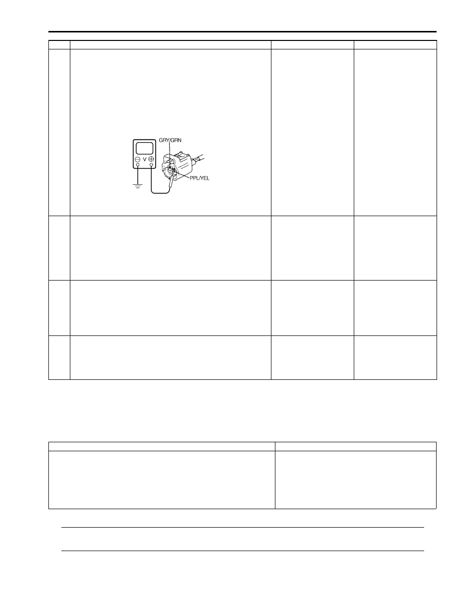
3
ECM voltage check
1) Disconnect connector from ECT sensor with ignition
switch turned OFF.
2) Check for proper connection to ECT sensor at “PPL/
YEL” and “GRY/GRN” wire terminals.
3) If OK, then turn ON ignition switch, measure voltage
between “PPL/YEL” wire terminal of ECT sensor
connector and vehicle body ground.
Is voltage about 4 – 6 V?
Go to Step 6.
Go to Step 4.
4
ECT sensor short circuit check
1) Disconnect connectors from ECM with ignition switch
turned OFF.
2) Measure resistance between “PPL/YEL” wire terminal of
ECT sensor connector and vehicle body ground.
Is resistance infinity?
Go to Step 5.
“PPL/YEL” wire is
shorted to ground
circuit.
If wire is OK, substitute
a known-good ECM and
recheck.
5
ECT sensor short circuit check
1) Turn ON ignition switch.
2) Measure voltage between “PPL/YEL” wire terminal of
ECT sensor connector and vehicle body ground.
Is voltage about 0 V?
Go to Step 6.
“PPL/YEL” wire is
shorted to other circuit.
If wire is OK, substitute
a known-good ECM and
recheck.
6
ECT sensor for performance check
1) Check ECT sensor according to “Engine Coolant
Temperature (ECT) Sensor Inspection in Section 1C”.
Is it in good condition?
Substitute a known-
good ECM and recheck.
Replace ECT sensor.
Step
Action
Yes
No
I5JB0A110040-01
DTC detecting condition
Trouble area
DTC will be set when all of following conditions are detected for 0.5
seconds continuously.
• Engine is running
• Voltage of ECT sensor output is more than specified value
(Low engine coolant temperature (high voltage / high resistance))
(1 driving cycle detection logic)
• ECT sensor circuit
• ECT sensor
• ECM
Нет комментариевНе стесняйтесь поделиться с нами вашим ценным мнением.
Текст