Suzuki Grand Vitara JB416 / JB420. Manual — part 34
1A-85 Engine General Information and Diagnosis:
DTC P0111: Intake Air Temperature Circuit Range / Performance
S5JB0A1104023
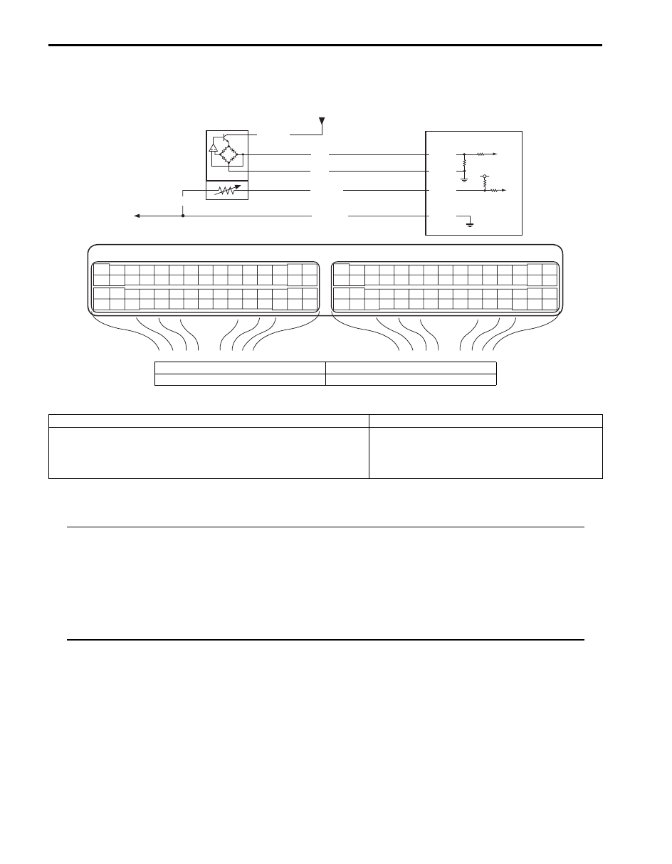
Wiring Diagram
DTC Detecting Condition and Trouble Area
DTC Confirmation Procedure
NOTE
Check to make sure that following conditions are satisfied when using this “DTC Confirmation
Procedure”.
• Intake air temperature at engine start: –10
°C (14 °F) to 80 °C (176 °F)
• Intake air temperature: –10
°C (14 °F) to 70 °C (158 °F)
• Engine coolant temperature at engine start: less than 30
°C (86 °F)
• Engine coolant temperature: 70
°C (158 °F) to 150 °C (302 °F)
• Altitude (barometric pressure): 2400 m, 8000 ft or less (560 mmHg, 75 kPa or more)
1) With ignition switch turned OFF, connect scan tool.
2) Turn ON ignition switch, clear DTC using scan tool.
3) Start engine and warm up to normal operating temperature. (ECT approx. 90 – 95
°C, 194 – 203 °F)
4) Run engine at idle speed for 10 min. or more.
5) Check DTC and pending DTC.
E23
C37
3
4
18
19
5
6
7
10
11
17
20
47
46
49
50
51
21
22
52
16
25
9
24
14
29
55
57
54 53
59
60
58
2
26
27
28
15
30
56
48
32
31
34
35
36
37
40
42
39 38
44
45
43
41
33
1
12
13
23
8
3
4
18
19
5
6
7
10
11
17
20
47
46
49
50
51
21
22
52
16
25
9
24
14
29
55
57
54 53
59
60
58
2
26
27
28
15
30
56
48
32
31
34
35
36
37
40
42
39 38
44
45
43
41
33
1
12
13
23
8
5V
LT GRN
GRY/GRN
GRY/GRN
1
BLU/BLK
C37-25
C37-57
3
BLU
RED
C37-26
C37-27
4
2
I5JB0A110036-01
1. MAF and IAT sensor
3. To other sensors
2. ECM
4. From main relay
DTC detecting condition
Trouble area
Difference of maximum IAT minus minimum IAT is less than 0.3
°C
(32.5
°F) while ECT is over 70 °C (158 °F) after 10 min from cold
engine start (ECT is lower than 30
°C (86 °F) at engine start).
(2 driving cycle detection logic)
• High resistance circuit
• MAF and IAT sensor
• ECM
Engine General Information and Diagnosis: 1A-86
DTC Troubleshooting
NOTE
Before this trouble shooting is performed, read the precautions for DTC troubleshooting referring to
“Precautions For DTC Troubleshooting”.
Step
Action
Yes
No
1
Was “Engine and Emission Control System Check”
performed?
Go to Step 2.
Go to “Engine and
Emission Control
System Check”.
2
IAT sensor and its circuit check
1) Connect scan tool to DLC with ignition switch turned
OFF.
2) Turn ignition switch to ON position.
3) Check intake air temp. displayed on scan tool.
Is –40
°
C (–40
°
F) or 119
°
C (246
°
F) indicated?
Go to Step 3.
Intermittent trouble.
Check for intermittent
referring to “Intermittent
and Poor Connection
Inspection in Section
00”.
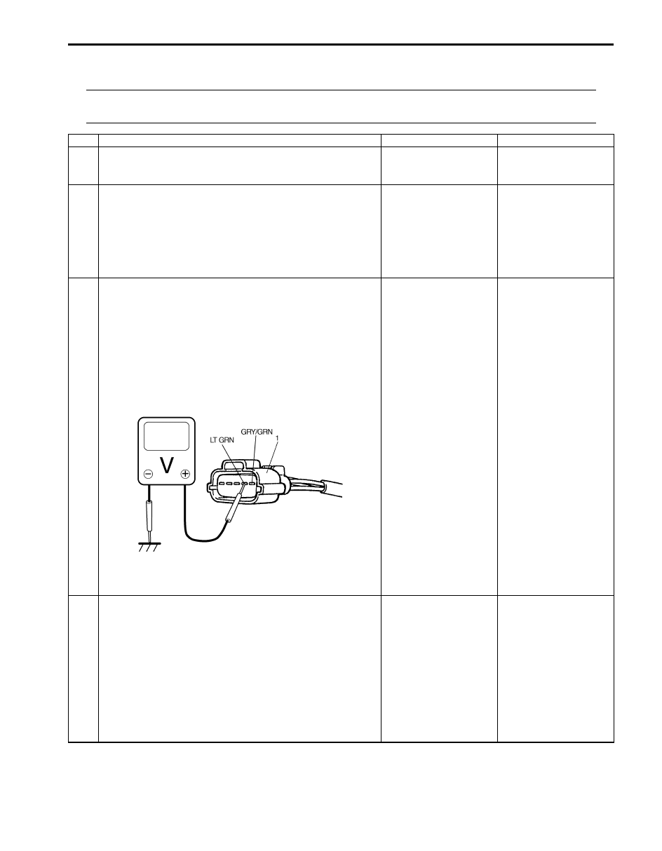
3
Wire harness check
1) Disconnect MAF and IAT sensor connector (1) with
ignition switch turned OFF.
2) Check for proper connection to MAF and IAT sensor
connector (1) at “LT GRN” and “GRY/GRN” wire
terminals.
3) If OK, then with ignition switch turned ON, measure
voltage between “LT GRN” wire terminal of MAF and IAT
sensor connector and vehicle body ground.
Is measured voltage applied to “LT GRN” wire terminal about
4 – 6 V?
Go to Step 8.
Go to Step 4.
4
ECM voltage check
1) Turn OFF ignition switch.
2) Remove ECM from its bracket with ECM connectors
connected.
3) Check for proper connection of ECM connector at “C37-
25” terminal.
4) If OK, then turn ON ignition switch, measure voltage
between “C37-25” terminal of ECM connector and
vehicle body ground.
Is voltage about 4 – 6 V at terminal?
“LT GRN” wire is open
circuit.
If wire and connection
are OK, go to Step 5.
Go to Step 5.
I5JB0A110037-02

1A-87 Engine General Information and Diagnosis:
5
Wire circuit check
1) Disconnect connectors from ECM with ignition switch
turned OFF.
2) Measure resistance between “LT GRN” wire terminal of
MAF and IAT sensor connector and vehicle body
ground.
Is resistance infinity?
Go to Step 6.
“LT GRN” wire is
shorted to ground or
other circuit.
If wire is OK, substitute
a known-good ECM and
recheck.
6
Wire circuit check
1) Turn ignition switch to ON position.
2) Measure voltage between “LT GRN” wire terminal of
MAF and IAT sensor connector and vehicle body
ground.
Is voltage about 0 V?
Go to Step 7.
“LT GRN” wire shorted
to other circuit.
If wire is OK, substitute
a known-good ECM and
recheck.
7
Wire circuit check
1) Measure resistance between “C37-25” terminal of ECM
connector and “LT GRN” wire terminal of MAF and IAT
sensor connector with ignition switch turned OFF.
Is resistance below 3
Ω
?
Go to Step 8.
“LT GRN” wire is high
resistance circuit.
8
Ground circuit check
1) Connect connectors to ECM.
2) Check for proper connection of MAF and IAT sensor
connector at “GRY/GRN” wire terminal.
3) Measure resistance between “GRY/GRN” wire terminal
of MAF and IAT sensor connector and vehicle body
ground with ignition switch turned OFF.
Is resistance below 5
Ω
?
Go to Step 10.
Go to Step 9.
9
Ground circuit check
1) Remove ECM from its bracket with ECM connectors
connected.
2) Measure resistance between “C37-57” terminal of ECM
connector and vehicle body ground.
Is resistance below 3
Ω
?
“GRY/GRN” wire is
open or high resistance
circuit.
Poor “C37-57”
connection.
Faulty ECM ground
circuit.
If circuit is OK,
substitute a known-
good ECM and recheck.
10 IAT sensor check
1) Check IAT sensor according to “Mass Air Flow (MAF)
and Intake Air Temperature (IAT) Sensor Inspection in
Section 1C”.
Is it in good condition?
Substitute a known-
good ECM and recheck.
Replace MAF and IAT
sensor.
Step
Action
Yes
No

Engine General Information and Diagnosis: 1A-88
DTC P0112: Intake Air Temperature Sensor Circuit Low
S5JB0A1104024
Wiring Diagram
Refer to “DTC P0111: Intake Air Temperature Circuit Range / Performance”.
DTC Detecting Condition and Trouble Area
DTC Confirmation Procedure
1) With ignition switch turned OFF, connect scan tool.
2) Turn ON ignition switch and clear DTC using scan tool.
3) Start engine and run it for 10 sec.
4) Check DTC and pending DTC.
DTC Troubleshooting
NOTE
Before this trouble shooting is performed, read the precautions for DTC troubleshooting referring to
“Precautions For DTC Troubleshooting”.
DTC detecting condition
Trouble area
DTC will be set when all of following conditions are detected for
0.5 seconds continuously.
• Engine is running
• Voltage of IAT sensor output is less than specified value
(High intake air temperature (low voltage / low resistance))
(1 driving cycle detection logic)
• IAT sensor circuit
• IAT sensor
• ECM
Step
Action
Yes
No
1
Was “Engine and Emission Control System Check”
performed?
Go to Step 2.
Go to “Engine and
Emission Control
System Check”.
2
IAT sensor and its circuit check
1) Connect scan tool to DLC with ignition switch turned
OFF.
2) Turn ON ignition switch.
3) Check intake air temp. displayed on scan tool.
Is 119
°
C (246
°
F) indicated?
Go to Step 3.
Intermittent trouble.
Check for intermittent
referring to “Intermittent
and Poor Connection
Inspection in Section
00”.
Нет комментариевНе стесняйтесь поделиться с нами вашим ценным мнением.
Текст