Suzuki Grand Vitara JB416 / JB420. Manual — part 221

5A-18 Automatic Transmission/Transaxle:
Diagnostic Information and Procedures
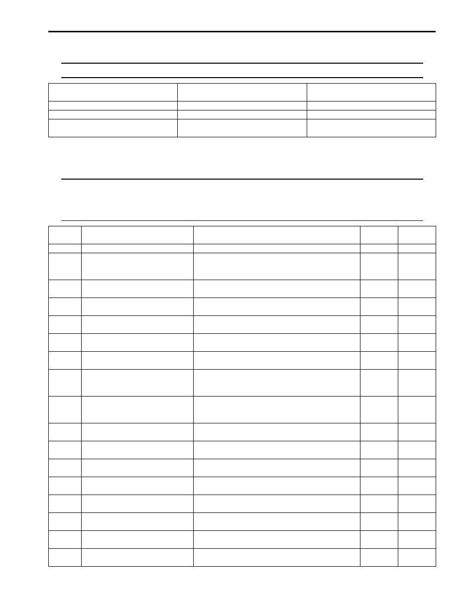
A/T System Check
S5JB0A5104001
Refer to the following items for the details of each step.
1. Engine
6. Transmission warning light (vehicle is
equipped with engine diagnosis
connector)
11. 4L/N low switch
16. Shift solenoid valve-B
2. Transmission
7. MIL (vehicle is not equipped with engine
diagnosis connector)
12. Pressure control solenoid valve
17. Valve body assembly
3. BCM
8. Input shaft speed sensor
13. TCC pressure control solenoid
valve
18. Transmission range sensor
4. Selector lever assembly
including “3” position
switch
9. Output shaft speed sensor
14. Shift solenoid valve-A
19. ECM
5. P/N mode switch
10. TCM
15. Transmission fluid temperature
sensor
20. AT relay included power
integration No.2 in main fuse
box
Step
Action
Yes
No
1
Customer complaint analysis
1) Perform customer complaint analysis.
Was customer complaint analysis performed according to
instruction?
Go to Step 2.
Perform customer
complaint analysis.
2
DTC / Freeze frame data check, record and clearance
1) Check for DTC (including pending DTC).
Is there any DTC(s)?
Print DTC and freeze
frame data or write them
down and clear them by
referring to “DTC
Clearance”.
Go to Step 3.
Go to Step 4.
3
Visual inspection
1) Perform visual inspection.
Is there any faulty condition?
Repair or replace
malfunction part.
Go to Step 11.
Go to Step 5.
4
Visual inspection
1) Perform visual inspection.
Is there any faulty condition?
Repair or replace
malfunction part.
Go to Step 11.
Go to Step 8.
5
Trouble symptom confirmation
1) Confirm trouble symptom.
Is trouble symptom identified?
Go to Step 6.
Go to Step 7.
6
Rechecking and record of DTC / Freeze frame data
1) Recheck for DTC and freeze frame data referring to
Is there any DTC(s)?
Go to Step 9.
Go to Step 8.
7
Rechecking and record of DTC / Freeze frame data
1) Recheck for DTC and freeze frame data referring to
Is there any DTC(s)?
Go to Step 9.
Go to Step 10.
8
A/T Basic Check and A/T Trouble Diagnosis
1) Check and repair according to “A/T Basic Check” and “A/
Are check and repair complete?
Go to Step 11.
Check and repair
malfunction part(s).
Go to Step 11.
9
Troubleshooting for DTC
1) Check and repair according to applicable DTC diag. flow.
Are check and repair complete?
Go to Step 11.
Check and repair
malfunction part(s).
Go to Step 11.
Automatic Transmission/Transaxle: 5A-19
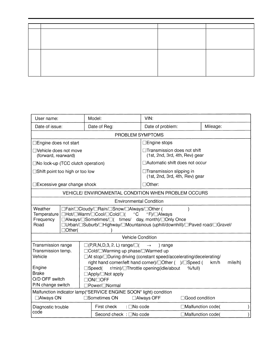
Step 1. Customer Complaint Analysis
Record details of the problem (failure, complaint) and how it occurred as described by the customer.
For this purpose, use of such a inspection form will facilitate collecting information to the point required for proper
analysis and diagnosis.
Customer problem inspection form (example)
10 ) Check for intermittent problem
1) Check for intermittent problem.
Is there any faulty condition?
Repair or replace
malfunction part(s).
Go to Step 11.
Go to Step 11.
11 ) Final confirmation test
1) Clear DTC if any.
2) Perform final confirmation test.
Is there any problem symptom, DTC or abnormal condition?
Go to Step 6.
End.
Step
Action
Yes
No
I5JB0A510015-01

5A-20 Automatic Transmission/Transaxle:
NOTE
The form is a standard sample. It should be modified according to conditions characteristic of each
market.
Step 2. DTC / Freeze Frame Data Check, Record and
Clearance
First, referring to “DTC Check”, check DTC (including
pending DTC). If DTC exists, print or write down DTC
and freeze frame data and then clear them by referring
to “DTC Clearance”. DTC indicates malfunction in the
system but it is not possible to know from it whether the
malfunction is occurring now or it occurred in the past
and normal condition has been restored. In order to
know that, check symptom in question according to Step
5 and then recheck DTC according to Step 6.
Diagnosing a trouble based on the DTC in this step only
or failure to clear the DTC in this step may result in an
faulty diagnosis, trouble diagnosis of a normal circuit or
difficulty in troubleshooting which is otherwise
unnecessary.
Step 3 and Step 4. Visual Inspection
As a preliminary step, be sure to perform visual check of
the items that support proper function of the A/T and
engine referring to “Visual Inspection”.
Step 5. Trouble Symptom Confirmation
Check trouble symptoms based on information obtained
in Step 1 ) “Customer Complaint Analysis” and Step 2
)
“DTC/Freeze Frame Data Check, Record and
Clearance”.
Also, recheck DTC according to “DTC Confirmation
Procedure” described in each DTC flow.
Step 6 and Step 7. Recheck and Record of DTC /
Freeze Frame Data
Refer to “DTC Check” for checking procedure.
Step 8. A/T Basic Check and A/T Trouble Diagnosis
Perform A/T basic check according to “A/T Basic Check”
first. When the end of the flow has been reached, check
the parts of the system suspected as a possible cause
referring to “A/T Symptom Diagnosis” and based on
symptoms appearing on the vehicle (symptoms obtained
through steps of customer complaint analysis, trouble
symptom confirmation and/or A/T basic check) and
repair or replace faulty parts, if any.
Step 9. Troubleshooting for DTC
Based on the DTC indicated in Step 6 and 7 and
referring to applicable DTC flow, locate the cause of the
trouble, namely in a sensor, switch, wire harness,
connector, actuator, TCM or other part and repair or
replace faulty parts.
Step 10. Check for Intermittent Problem
Check parts where an intermittent trouble is easy to
occur (e.g., wire harness, connector, etc.), referring to
“Intermittent and Poor Connection Inspection in Section
00” and related circuit of DTC recorded in Step 2.
Step 11. Final Confirmation Test
Confirm that the problem symptom has gone and the A/T
is free from any abnormal conditions.
If what has been repaired is related to the malfunction
DTC, clear the DTC once, set conditions under which
DTC was detected and A/T and/or vehicle was repaired
and confirm that no DTC is indicated.
Malfunction Indicator Lamp (MIL) Check
S5JB0A5104002
Refer to “Malfunction Indicator Lamp (MIL) Check in
Section 1A”.
Transmission Warning Light Operation Check
(Vehicle is Equipped with Engine Diagnosis
Connector)
S5JB0A5104003
1) Turn ignition switch ON.
2) Check that transmission warning light lights for about
2 – 4 sec. and then goes OFF. If anything faulty is
found, advance “Transmission Warning Light Circuit
Check – Light Does Not Come “ON” at Ignition
Switch ON (Vehicle is equipped with engine
diagnosis connector)” or “Transmission Warning
Light Circuit Check – Light Remains “ON” at Ignition
Switch ON (Vehicle is equipped with engine
diagnosis connector)”.
“POWER” Lamp Operation Check
S5JB0A5104004
1) Turn ignition switch ON.
2) Check that “POWER” lamp lights for about 2 – 4 sec.
and then goes OFF.
If anything faulty is found, advance to ““POWER”
Light Circuit Check – Light Does Not Come “ON” at
Ignition Switch ON”.
Automatic Transmission/Transaxle: 5A-21
DTC Table
S5JB0A5104005
NOTE
Confirmation available table of automatic transmission related DTC is shown below.
{
: Available-DTC can be confirmed
X: Not available-DTC can not be confirmed
NOTE
A: Driving cycles when MIL lighting and storing DTC in TCM memory for vehicle is not equipped with
engine diagnosis connector.
B: Driving cycles when transmission warning light lighting and storing DTC in TCM memory for
vehicle is equipped with engine diagnosis connector.
Vehicle is not equipped with engine
diagnosis connector
Vehicle is equipped with engine
diagnosis connector
SUZUKI scan tool
{
{
Generic scan tool
{
X
Not using scan tool (if equipped with
A/T monitor connector)
X
{
DTC No.
Detecting item
Detecting condition (DTC will set when
detecting)
A
B
0000
No malfunction is detected
—
—
—
P0705
Transmission Range Sensor
Circuit Malfunction (PRNDL
Input)
Multiple signals are inputted simultaneously.
1driving
cycle
1driving
cycle
P0707
Transmission Range Sensor
Circuit Low
No sensor signal is inputted.
2 driving
cycles
2 driving
cycles
P0712
Transmission Fluid Temperature
Sensor “A” Circuit Low
Sensor output voltage is too low.
1driving
cycle
1driving
cycle
P0713
Transmission Fluid Temperature
Sensor “A” Circuit High
Sensor output voltage is too high.
1driving
cycle
1driving
cycle
P0717
Input / Turbine Speed Sensor
Circuit No Signal
No sensor signal is detected although output
speed sensor signal is inputted.
1driving
cycle
1driving
cycle
P0722
Output Speed Sensor Circuit No
Signal
No sensor signal is inputted although input speed
sensor signal is inputted.
1driving
cycle
1driving
cycle
P0741
Torque Converter Clutch Circuit
Performance or Stuck Off
Difference in revolution between engine and input
shaft is too large although TCM is commanding
TCC pressure control solenoid to turn ON.
2 driving
cycles
2 driving
cycles *2
P0742
Torque Converter Clutch Circuit
Stuck On
Difference in revolution between engine and input
shaft is too small although TCM is commanding
TCC pressure control solenoid to turn OFF.
2 driving
cycles
2 driving
cycles *2
P0751
Shift Solenoid “A” Performance
or Stuck Off
The gear commanded by TCM does not match
the actual gear when driving.
2 driving
cycles
2 driving
cycles *2
P0752 Shift Solenoid “A” Stuck On
The gear commanded by TCM does not match
the actual gear when driving.
2 driving
cycles
2 driving
cycles *2
P0756
Shift Solenoid “B” Performance
or Stuck Off
The gear commanded by TCM does not match
the actual gear when driving.
2 driving
cycles
2 driving
cycles *2
P0757 Shift Solenoid “B” Stuck On
The gear commanded by TCM does not match
the actual gear when driving.
2 driving
cycles
2 driving
cycles *2
P0962
Pressure Control Solenoid “A”
Control Circuit Low
No electric flow is detected on pressure control
solenoid circuit.
1driving
cycle
1driving
cycle
P0963
Pressure Control Solenoid “A”
Control Circuit High
Too much electric flow is detected on pressure
control solenoid circuit.
1driving
cycle
1driving
cycle
P0973
Shift Solenoid “A” Control Circuit
Low
Voltage of shift solenoid terminal is low although
TCM is commanding shift solenoid to turn ON.
1driving
cycle
1driving
cycle
P0974
Shift Solenoid “A” Control Circuit
High
Voltage of shift solenoid terminal is high although
TCM is commanding shift solenoid to turn OFF.
1driving
cycle
1driving
cycle
Нет комментариевНе стесняйтесь поделиться с нами вашим ценным мнением.
Текст