Suzuki Grand Vitara JB416 / JB420. Manual — part 222
5A-22 Automatic Transmission/Transaxle:
NOTE
*1: MIL does not light although DTC is detected and stored.
*2: Transmission warning light does not light although DTC is detected and stored.
DTC Check
S5JB0A5104006
NOTE
For vehicle without engine diagnosis
connector, the MIL is turned on when the
ECM and/or TCM detect malfunction(s). Each
ECU stores diagnostic information as the
diagnostic trouble code (DTC) in its memory
and outputs the DTC to the scan tool.
Therefore, check both of the ECUs for any
DTC with the scan tool because the DTC
stored in ECU and TCM is not read and
displayed at a time. However, each of the
ECUs needs not to be checked with the
generic scan tool because the DTC stored in
ECM and TCM is read and displayed at a time.
Automatic transmission DTC can be checked using any
one of the following 2 methods.
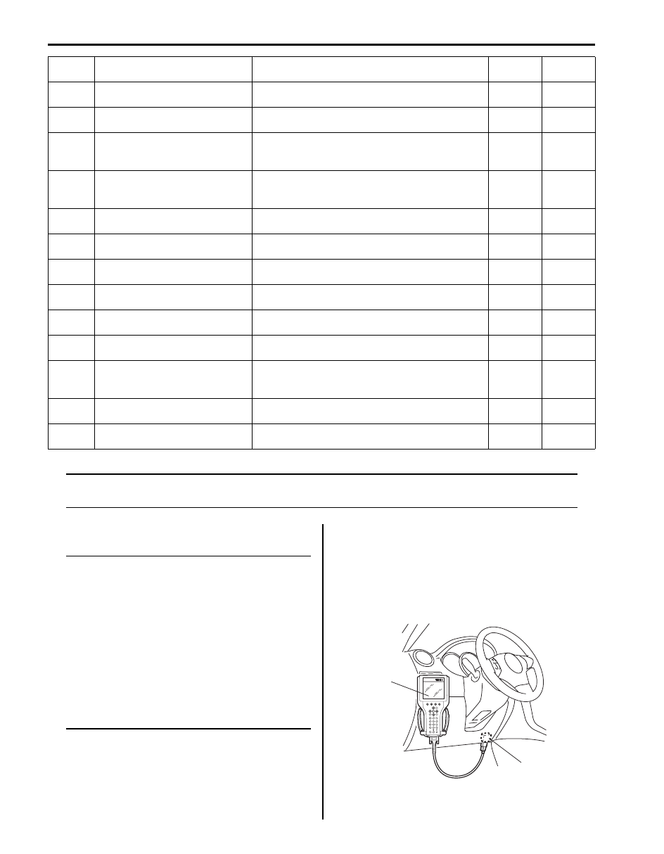
Reading DTC Using SUZUKI Scan Tool
1) Turn ignition switch OFF.
2) Connect SUZUKI scan tool to data link connector
(DLC).
Special tool
(A): SUZUKI scan tool
P0976
Shift Solenoid “B” Control Circuit
Low
Voltage of shift solenoid terminal is low although
TCM is commanding shift solenoid to turn ON.
1driving
cycle
1driving
cycle
P0977
Shift Solenoid “B” Control Circuit
High
Voltage of shift solenoid terminal is high although
TCM is commanding shift solenoid to turn OFF.
1driving
cycle
1driving
cycle
P1702
Internal Control Module Memory
Check Sum Error
Calculation of current data stored in TCM is not
correct comparing with pre-stored checking data
in TCM.
1driving
cycle
1driving
cycle
P1703 CAN Invalid Data- TCM
TCM receives malfunction signal of throttle
position, engine coolant temperature, engine
revolution and engine torque from ECM.
1driving
cycle *1
1driving
cycle *2
P1723 Range Select Switch Malfunction
3 position switch signal is inputted out of specified
value.
1driving
cycle *1
1driving
cycle *2
P1774
Control Module Communication
Bus OFF
Transmitting error detected to TCM for specified
time continuously.
1driving
cycle
1driving
cycle
P1777
TCM Lost Communication with
ECM (Reception Error)
Receiving error from ECM detected to TCM for
specified time continuously.
1driving
cycle
1driving
cycle
P1778
TCM Lost Communication with
BCM (Reception Error)
Receiving error from BCM detected to TCM for
specified time continuously.
1driving
cycle *1
1driving
cycle *2
P1874
4L switch circuit malfunction
(Short)
Actual transfer position is 4H although transfer
low signal is inputted.
1driving
cycle
1driving
cycle *2
P1875
4L switch circuit malfunction
(Open)
Actual transfer position is 4L or N although
transfer low signal is not inputted.
1driving
cycle
1driving
cycle *2
P1878
Torque Converter Clutch
Shudder
Variation in the output revolution speed of the
specified amplitude and specified cycle is
detected under slip lock-up condition.
20driving
cycle *1
—
P2763
Torque Converter Clutch Circuit
High
Too much electric flow is detected on TCC
pressure control solenoid circuit.
1driving
cycle
1driving
cycle
P2764
Torque Converter Clutch Circuit
Low
No electric flow is detected on TCC pressure
control solenoid circuit.
1driving
cycle
1driving
cycle
DTC No.
Detecting item
Detecting condition (DTC will set when
detecting)
A
B
(A)
1
I5JB0A510016-01
Automatic Transmission/Transaxle: 5A-23
3) Read DTC according to instructions displayed on
SUZUKI scan tool and write it down. Refer to
SUZUKI scan tool operator’s manual for further
details.
4) After completing the check, turn ignition switch OFF
and disconnect SUZUKI scan tool from data link
connector (DLC).
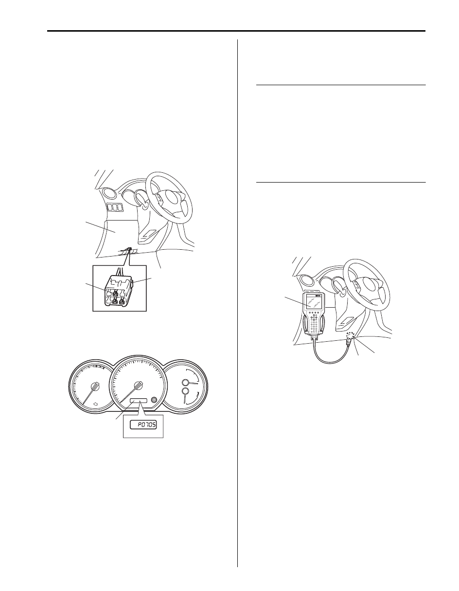
Reading DTC Using Monitor Connector (If Equipped)
1) Turn ignition switch OFF.
2) Remove steering column hole cover (1).
3) Using service wire, connect diagnosis switch
terminal (3) of monitor connector (2) to body ground.
4) With ignition switch ON position and leaving engine
OFF, read DTC displayed on digital display odometer
(1) referring to “DTC Table”.
5) After completing the check, turn ignition switch OFF
and disconnect service wire from monitor connector.
DTC Clearance
S5JB0A5104007
Automatic transmission DTC can be cleared using any
one of the following 2 methods.
NOTE
DTC and freeze frame data stored in TCM
memory are also cleared in following cases.
Be careful not to clear them before keeping
their record.
• When power to TCM is cut off (by
disconnecting battery cable, removing
fuse or disconnecting TCM connector).
• When the same malfunction (DTC) is not
detected again during 40 engine warm-up
cycles.
DTC Clearance Using SUZUKI Scan Tool
1) Turn ignition switch OFF.
2) Connect SUZUKI scan tool to data link connector
(DLC) (1).
Special tool
(A): SUZUKI scan tool
3) Clear DTC according to instructions displayed on
SUZUKI scan tool. Refer to SUZUKI scan tool
operator’s manual for further details.
4) After completing the clearance, turn ignition switch
OFF and disconnected SUZUKI scan tool from data
link connector (DLC).
3
1
2
I5JB0A510017-01
1
I5JB0A510018-01
(A)
1
I5JB0A510016-01
5A-24 Automatic Transmission/Transaxle:
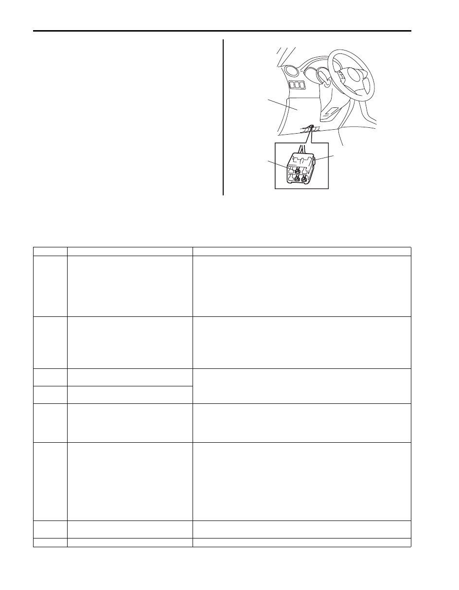
DTC Clearance Using Monitor Connector (If
Equipped)
1) Remove steering column hole cover (1).
2) Turn ignition switch ON.
3) After 6 seconds or more, repeat connecting and
disconnecting diagnosis switch terminal (3) of
monitor connector (2) and body ground 5 times at
about 1 second interval within 10 seconds, using
service wire.
4) Check TCM that no malfunction DTC remains in
memory of it.
Fail Safe Table
S5JB0A5104008
This function is provided by the safe mechanism that assures safe driveability even when the solenoid valve, sensor or
its circuit fails. The following table shows the fail safe function for each fail condition of sensor, solenoid, TCM or its
circuit.
3
1
2
I5JB0A510017-01
DTC No.
Trouble Area
Fail Safe Operation
P0705
Transmission Range Sensor Circuit
Malfunction (PRNDL Input)
• TCM control is performed in priority order below.
3> D> 2> L> R> N> P
• Slip controlled lock-up function is inhibited to operate.
• Reverse control is inhibited.
• Cruise control function is inhibited to operate.
• Power mode is inhibited.
P0707
Transmission Range Sensor Circuit
Low
• Range is assumed to be “D” range.
• Slip controlled lock-up function is inhibited to operate.
• Reverse control is inhibited.
• Cruise control function is inhibited to operate.
• Power mode is inhibited.
P0712
Transmission Fluid Temperature
Sensor “A” Circuit Low
• A/T fluid temperature is assumed to be 80
°C (176 °F).
• Lock-up function is inhibited to operate.
• Line pressure control at gear shifting is inhibited.
P0713
Transmission Fluid Temperature
Sensor “A” Circuit High
P0717
Input / Turbine Speed Sensor Circuit
No Signal
• Torque reducing request to ECM (torque reduction control) is
inhibited.
• Lock-up function is inhibited to operate.
• Line pressure control at gear shifting is inhibited.
P0722
Output Speed Sensor Circuit No
Signal
• Vehicle speed which is calculated by input shaft speed sensor
signal is used for gear shifting control instead of vehicle speed
calculated by output shaft speed sensor (VSS) signal.
• Upshifting to 4th gear is inhibited.
• Lock-up function is inhibited to operate.
• Torque reducing request to ECM (torque reduction control) is
inhibited.
• Line pressure control at gear shifting is inhibited.
P0742
Torque Converter Clutch Circuit Stuck
On
When vehicle speed is less than 10 km/h (6 mile/h), gear position is
fixed in 1st gear for prevention of engine stall.
P0752 Shift Solenoid “A” Stuck On
Upshifting to 4th gear is inhibited.

Automatic Transmission/Transaxle: 5A-25
P0962
Pressure Control Solenoid “A” Control
Circuit Low
• Power supply for all solenoid valves is cut.
• Gear position is fixed according to select lever position as shown
in the following.
R: Reverse
D: 4th
3: 4th
2: 3rd
L: 1st
• Lock-up function is inhibited to operate.
• Line pressure control at gear shifting is inhibited.
P0963
Pressure Control Solenoid “A” Control
Circuit High
P0973 Shift Solenoid “A” Control Circuit Low
P0974 Shift Solenoid “A” Control Circuit High
P0976 Shift Solenoid “B” Control Circuit Low
P0977
Shift Solenoid “B” Control Circuit High
P1702
Internal Control Module Memory
Check Sum Error
• Power supply for all solenoid valves is cut.
• Gear position is fixed according to select lever position as shown
in the following.
R: Reverse
D: 4th
3: 4th
2: 3rd
L: 1st
• Lock-up function is inhibited to operate.
• Line pressure control at gear shifting is inhibited.
P1703
CAN Invalid Data- TCM
In case of throttle position signal malfunction:
• Throttle opening used for line pressure control is assumed to be
100%.
• Throttle opening used for gear shifting control is assumed to be
0%.
• Lock-up function is inhibited to operate.
• Line pressure control at gear shifting is inhibited.
In case of engine coolant temperature signal malfunction:
• Engine coolant temperature is assumed to be 80
°C (176 °F).
• Slip controlled lock-up function is inhibited to operate.
In case of engine revolution signal malfunction:
• Engine revolution is assumed to be maximum revolution.
• Lock-up function is inhibited to operate.
In case of engine torque signal malfunction:
• Slip controlled lock-up function is inhibited to operate.
• Engine torque is assumed to be maximum torque.
In case of vehicle speed signal:
• Cruise control function is inhibited to operate.
P1774 CAN communication problem-TCM
• Throttle opening used for line pressure control is assumed to be
100%.
• Throttle opening used for gear shifting control is assumed to be
0%.
• Engine revolution is assumed to be maximum revolution.
• Engine torque is assumed to be maximum torque.
• Engine coolant temperature is assumed to be 80
°C (176 °F).
• Lock-up function is inhibited to operate.
• Line pressure control at gear shifting is inhibited.
• Torque reducing request to ECM (torque reduction control) is
inhibited.
• Line pressure is outputted maximum value.
• Power mode is inhibited. (P1774 only)
P1777
TCM Lost Communication with ECM
(Reception Error)
P1778
TCM Lost Communication with BCM
(Reception Error)
Power mode is inhibited.
DTC No.
Trouble Area
Fail Safe Operation
Нет комментариевНе стесняйтесь поделиться с нами вашим ценным мнением.
Текст