Suzuki Grand Vitara JB416 / JB420. Manual — part 373
9C-1 Instrumentation / Driver Info. / Horn:
Body, Cab and Accessories
Instrumentation / Driver Info. / Horn
Precautions
Precautions in Diagnosing Troubles for Combination Meter
S5JB0A9300001
• Combination meter uses signals (information) from each control module by CAN communication to control
speedometer, tachometer, fuel meter, engine coolant temp meter, warning light and indicator light (other than air
bag warning light, headlight leveling warning light, rear fog light and turn signal indicator lamp). Therefore, check
that no DTC is detected in each module before performing combination meter symptom diagnosis. If any DTC is
detected, correct trouble indicated by that DTC troubleshooting first.
• Seat belt reminder can be canceled by scan tool or specified procedure. If neither warning buzzer nor seat belt
reminder light operates, first confirm that seat belt reminder is not selected referring to “Scan Tool Data in Section
10B”. For further details, refer to “Seat Belt Construction in Section 8A”.
General Description
CAN Communication Data of Combination Meter
S5JB0A9301001
Combination meter communicates with each control module about the following information. For details of CAN
communication, refer to “CAN Communication System Description in Section 1A”.
• Data from ECM
– Engine revolution speed signal
– Engine coolant temperature signal
– Vehicle speed signal
– Malfunction indicator lamp (MIL) control signal
– Immobilizer indicator lamp control signal
– Fuel level signal
– “CRUSE” and “SET” indicator lamp control signal (if equipped)
– Diagnostic trouble code (DTC) of ECM
• Data from TCM (A/T model)
– Transmission range sensor signal (A/T selector lever position indicator)
– Malfunction indicator lamp (MIL) control signal
– Automatic transmission mode indicator lamp control signal
– Diagnostic trouble code (DTC) of TCM
• Data from BCM
– Brake fluid level switch signal (brake warning light control signal)
– Parking brake switch signal (brake warning light control signal)
– Driver side seat belt buckle switch signal (Seat belt warning light control signal)
– Charging system warning lamp signal (Charge warning light control signal)
– Engine oil pressure switch signal (Oil pressure warning light control signal)
– Lighting switch signal (illumination indicator light control signal)
– Door switch signal (door ajar warning lamp)
– HI beam indicator control signal
– Diagnostic trouble code (DTC) of BCM
• Data from 4WD control module (if equipped)
– 4WD shift position indicator lamp control signal
– Diagnostic trouble code (DTC) of 4WD control module

Instrumentation / Driver Info. / Horn: 9C-2
• Data from ABS control module (if equipped)
– ABS warning lamp control signal
– EBD warning light control signal (brake warning light control signal)
– Diagnostic trouble code (DTC) of ABS hydraulic unit/control module
• Data from keyless start control module (if equipped)
– Key indicator lamp control signal
Schematic and Routing Diagram
Combination Meter Circuit Diagram
S5JB0A9302001
8
11
12
13
14
7
6
5
4
G28-8
G28-10
9
9
G28-22
16
G28-16
1
2
10
G28-13
G28-14
G28-19
G28-11
3
G28-20
3
3
G28-15
G28-12
15
17
18
I5JB0A930001-04
1. Main fuse
6. Fuel meter
11. CPU
16. Illumination cancel switch (if equipped)
2. METER fuse
7. ECT meter
12. Power supply
17. Combination meter
3. Combination switch
8. ODO-TRIP
13. Interface circuit
18. Headlight auto leveling control module
4. Tacho meter
9. Junction connector
14. CAN driver
5. Speedometer
10. SDM
15. Stepper motor and LED output driver

9C-3 Instrumentation / Driver Info. / Horn:
Terminal arrangement of coupler viewed from combination meter side
Component Location
Audio System Component Location
S5JB0A9303001
Terminal
Circuit
Terminal
Circuit
G28-1
—
G28-12 To headlight auto leveling control module
G28-2
—
G28-13 Power source
G28-3
—
G28-14 Backup power source
G28-4
—
G28-15 GND
G28-5
—
G28-16 To SDM (Air bag warning lamp signal)
G28-6
—
G28-17
—
G28-7
—
G28-18
—
G28-8
CAN communication line (Active Low Signal)
G28-19 To turn signal light switch (turn L)
G28-9
—
G28-20 To turn signal light switch (turn R)
G28-10 CAN communication line (Active High Signal)
G28-21
—
G28-11 To rear fog light switch
G28-22 To illumination cancel switch
17 16
11
1
22
10
21
9
20
8
19
7
18
6
15
5
14
4
13
3
12
2
I5JB0A930002-01
2
1
4
3
3
6
5
2
(a)
7
I5JB0A930003-01
1. Radio or navigation assembly
4. Antenna feeder
7. GPS antenna (if equipped)
2. Front speaker
5. Antenna
: 10 N
⋅m (1.0 kgf-m, 7.5 lb-ft)
3. Rear speaker
6. Antenna base
Instrumentation / Driver Info. / Horn: 9C-4
Diagnostic Information and Procedures
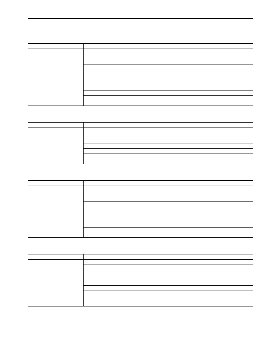
Speedometer Symptom Diagnosis
S5JB0A9304022
Tacho meter Symptom Diagnosis
S5JB0A9304023
Engine Coolant Temperature (ECT) Meter Symptom Diagnosis
S5JB0A9304024
Fuel Meter Symptom Diagnosis
S5JB0A9304025
Condition
Possible cause
Correction / Reference Item
Speedometer shows no
operation or incorrect
operation
Circuit fuse blown
Replace fuse and check for short circuit.
Data (information) can not be received
by CAN communication
Check ECM for DTC referring to “DTC Check
in Section 1A”.
Rear wheel speed sensor or sensor ring
faulty
Check rear wheel speed sensor or sensor ring
referring to “Rear Wheel Speed Sensor
Inspection in Section 4E” or “Rear Wheel
Encoder On-Vehicle Inspection in Section 4E”.
Wiring or ground faulty
Repair circuit.
Combination meter faulty
Replace combination meter.
ECM faulty
Replace after making sure that none of above
parts is faulty.
Condition
Possible cause
Correction / Reference Item
Tacho meter shows no
operation or incorrect
operation
Circuit fuse blown
Replace fuse and check for short circuit.
Data (information) can not be received
by CAN communication
Check ECM for DTC referring to “DTC Check
in Section 1A”.
Wiring or ground faulty
Repair circuit.
Combination meter faulty
Replace combination meter.
ECM faulty
Replace after making sure that none of above
parts is faulty.
Condition
Possible cause
Correction / Reference Item
Engine coolant
temperature (ECT) meter
shows no operation or
incorrect operation
Circuit fuse blown
Replace fuse and check for short circuit.
Data (information) can not be received
by CAN communication
Check ECM for DTC referring to “DTC Check
in Section 1A”.
ECT sensor faulty
Check ECT sensor referring to “Engine
Coolant Temperature (ECT) Sensor Inspection
in Section 1C”.
Wiring or ground faulty
Repair circuit.
Combination meter faulty
Replace combination meter.
ECM faulty
Replace after making sure that none of above
parts is faulty.
Condition
Possible cause
Correction / Reference Item
Fuel meter shows no
operation or incorrect
operation
Circuit fuse blown
Replace fuse and check for short circuit.
Data (information) can not be received
by CAN communication
Check ECM for DTC referring to “DTC Check
in Section 1A”.
Fuel level sensor faulty
Check fuel level sensor referring to “Fuel Level
Sensor Inspection”.
Wiring or ground faulty
Repair circuit.
Combination meter faulty
Replace combination meter.
ECM faulty
Replace after making sure that none of above
parts is faulty.
Нет комментариевНе стесняйтесь поделиться с нами вашим ценным мнением.
Текст