Suzuki Grand Vitara JB416 / JB420. Manual — part 277
7A-14 Heater and Ventilation:
Center Ventilation Louver Removal and
Installation
S5JB0A7106020
Removal
1) Disconnect negative (–) cable at battery.
2) Disable air bag system referring to “Disabling Air
3) Remove center garnish with audio unit and HVAC
control module referring to “Audio Unit Removal and
Installation in Section 9C”.
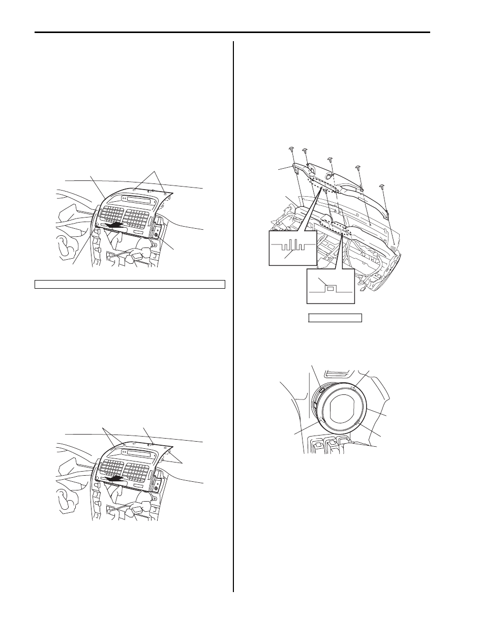
4) Remove mounting screw (1) and then pull off center
ventilation louver (2).
5) Disconnect connectors and remove center
ventilation louver.
6) Remove center ventilation louver from center
garnish.
Installation
Reverse removal procedure, noting the following item.
Insert backside of center ventilation louver to ventilator
duct surely.
• When installing center ventilation louver, align boss
(1) and claws (2) with installation hole of instrument
panel.
• Enable air bag system referring to “Enabling Air Bag
Side Ventilation Louver Removal and
Installation
S5JB0A7106021
Removal
1) Remove steering column hole cover.
2) Remove instrument panel referring to “Instrument
Panel Removal and Installation in Section 9C”.
3) Remove screws and claws (3), and then remove
defroster duct (2) from instrument panel.
4) Remove ventilator duct (1) from instrument panel.
5) Remove side ventilation louver (1) from instrument
panel while pressing claws (2).
3. Clip
1
1
2
3
I5JB0A710020-01
2
2
1
I5JB0A710021-01
4. hole
2
1
3
4
I5JB0A710022-02
2
1
2
2
2
I5JB0A710023-01

Heater and Ventilation: 7A-15
Installation
1) Reverse removal procedure, noting the following.
• Install side ventilation louver (1) to instrument
panel (2) as shown in figure.
• When installing defroster duct to instrument panel,
put claws of defroster duct into hole of ventilator
duct surely.
Rear Duct Components
S5JB0A7106022
Rear Duct Removal and Installation
S5JB0A7106023
Removal
1) Disconnect negative (–) cable at battery.
2) Remove front seats.
3) Remove console box.
4) Take off carpet till rear ducts is totally exposed.
5) Remove rear ducts (1).
Installation
Reverse removal procedure noting the following.
• Insert boss (1) of duct into hole of floor member (2).
1. Rear duct
1
2
1
2
I5JB0A710024-02
1
I5JB0A710025-02
1
I5JB0A710026-01
2
1
I5JB0A710027-01

7B-1 Air Conditioning System:
HVAC
Air Conditioning System
Precautions
A/C System Caution
S5JB0A7200004
CAUTION
!
The air conditioning system of this vehicle
uses refrigerant HFC-134a (R-134a).
None of refrigerant, compressor oil and
component parts is interchangeable between
two types of A/C: one using refrigerant HFC-
134a (R-134a) and the other using refrigerant
CFC-12 (R-12).
Be sure to check which refrigerant is used
before any service work including inspection
and maintenance. For identification between
these two types, refer to “A/C Refrigerant
Type Description”.
When replenishing or changing refrigerant
and compressor oil and when replacing
parts, make sure that the material or the part
to be used is appropriate to the A/C installed
in the vehicle being serviced.
Use of incorrect one will result in leakage of
refrigerant, damage in parts or other faulty
condition.
Precautions on Servicing A/C System
S5JB0A7200005
WARNING
!
Should refrigerant HFC-134a (R-134a) is
exposed to your eye(s), consult a doctor
immediately.
• Do not use your hand to rub affected
eye(s). Instead, use fresh cold water to
splash it over affected area to thus
gradually raise its temperature above the
freezing point.
• Obtain proper treatment as soon as
possible from a doctor or eye specialist.
Should liquid refrigerant HFC-134a (R-
134a) is exposed to your skin, such
affected part should be treated in the same
manner as when skin is frostbitten or
frozen.
Precautions in Diagnosing Trouble
S5JB0A7200006
• Do not disconnect connector from HVAC control
module, battery cable from battery, or main fuse
before reading diagnostic information stored in HVAC
control module memory.
• When diagnosing vehicle indoors, sunload sensor has
to be lighted over vertically with an incandescent
lamp. Otherwise, DTC is detected even if sunload
sensor is normal.
• Diagnostic information (diagnostic trouble code)
stored in HVAC control module can be checked by
display of HVAC control module. Also, it can be
checked by using SUZUKI scan tool. Before checking
diagnostic information (diagnostic trouble code), read
this manual and operator’s manual for SUZUKI scan
tool to know how to read diagnostic information
(diagnostic trouble code).
• When trouble is diagnosed using diagnostic
information (diagnostic trouble code) on display of
HVAC control module, keep in your mind that each
diagnostic information (diagnostic trouble code) has
priority, and only diagnostic information (diagnostic
trouble code) which has the highest priority is
indicated. Therefore, after troubleshooting the
malfunction, make sure if there exists any other
diagnostic information (diagnostic trouble code).
• After troubleshooting some trouble, DTC can be
stored in HVAC control module memory as history
DTC.
• Be sure to read “Precautions for Electrical Circuit
Service” before inspection.
Precautions on Handling Refrigerant HFC-134a
(R-134a)
S5JB0A7200007
• When handling refrigerant, always wear goggles to
protect your eyes.
• Avoid you direct contact to liquid refrigerant.
• Do not heat refrigerant container higher than 40
°C
(104
°F).
• Do not discharge refrigerant into atmosphere.
• Do not allow liquid refrigerant to touch bright metals.
Refrigerant combined with moisture is corrosive and
will tarnish surfaces of bright metals including chrome.
• After recovering refrigerant from system, the amount
of compressor oil removed must be measured and the
same amount added to the system.
Air Conditioning System: 7B-2
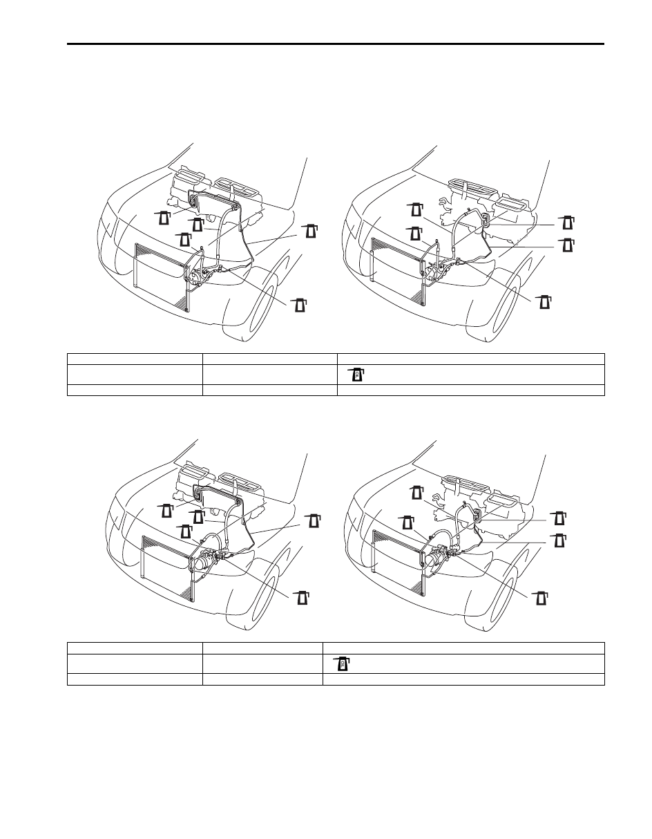
Precautions on Servicing Refrigerant Line
S5JB0A7200008
• When connecting hoses and pipes, apply a few drops of compressor oil (refrigerant oil) to seats of coupling nuts
and O-ring.
For M16 engine model
For J20 engine model
4
[A]
[B]
OIL
1
OIL
1
OIL
2
OIL
2
OIL
3
OIL
4
OIL
3
OIL
5
OIL
5
OIL
I5JB0A720001-02
[A]: LH steering vehicle
2. Discharge hose
5. Pressure sensor
[B]: RH steering vehicle
3. Liquid pipe
: Apply compressor oil (refrigerant oil) to O-ring.
1. Suction hose
4. Expansion valve
4
OIL
1
OIL
2
OIL
3
[A]
[B]
OIL
5
OIL
1
OIL
2
OIL
4
OIL
3
OIL
5
OIL
I5JB0A720002-02
[A]: LH steering vehicle
2. Discharge hose
5. Pressure sensor
[B]: RH steering vehicle
3. Liquid pipe
: Apply compressor oil (refrigerant oil) to O-ring.
1. Suction hose
4. Expansion valve
Нет комментариевНе стесняйтесь поделиться с нами вашим ценным мнением.
Текст