Suzuki Grand Vitara JB416 / JB420. Manual — part 278
7B-3 Air Conditioning System:
• Never use heat for bending pipes. When bending a pipe, try to make its bending radius as slight as possible.
• Keep internal parts of air conditioning free from moisture and dirt. When disconnecting any line from system, install
a blind plug or cap to the fitting immediately.
• When tightening or loosening a fitting, use two wrenches, one for turning and the other for support.
• Tighten bolts to specified torque.
Tightening torque
Refrigerant line bolt: 12 N·m (1.2 kgf-m, 9.0 lb-ft)
• Route drain hose so that drained water does not make any contact to vehicle components.
Precautions on Refrigerant Recovery
S5JB0A7200009
When discharging refrigerant out of A/C system, always
recover it by using refrigerant recovery and recycling
equipment. Discharging refrigerant HFC-134a (R-134a)
into atmosphere would cause adverse effect to
environments.
NOTE
When handling recovery and recycling
equipment, be sure to follow the instruction
manual for the equipment.
Precautions on Refrigerant Charge
S5JB0A7200010
Charge a proper amount of refrigerant to A/C system
according to charging procedure described in recovery,
evacuation and charging. Refer to “Charge” in
“Operation Procedure for Charging A/C with
Refrigerant”.
Precautions on Replenishing Compressor Oil
S5JB0A7200011
When replacing air conditioning parts with new ones, it is
necessary to replenish oil by the amount supposedly
remaining in each part.
When Charging Refrigerant Only
When charging refrigerant without replacing any
component, replenish the same amount of measured oil
when recovering refrigerant (if not measure, replenish 20
cm
3
(20 cc) oil).
When Replacing Compressor
CAUTION
!
Be sure to use specified compressor oil or an
equivalent compressor oil.
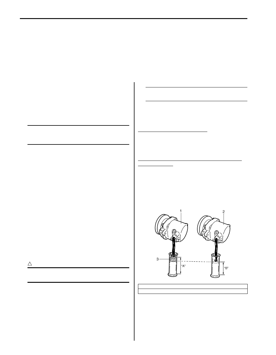
Compressor oil is sealed in each new compressor (1) by
the amount required for air conditioner cycle. Therefore,
when using a new compressor for replacement, drain oil
from it by the amount calculated as follows.
“C” = “A” – “B”
“C”: Amount of oil to be drained
“A”: Amount of oil sealed in a new compressor
“B”: Amount of oil remaining in removed
compressor
NOTE
Compressor assembly supplied from factory
is filled up with the following amount of oil.
: Compressor oil 99000–99015–00A
(MATSUSHITADENKI GU10) (M16 engine model)
: Compressor oil 99000–99022–00E (Compressor oil
(DH-PS, 250cc)) (J20 engine model)
Amount of oil in new compressor
M16 engine model: 120 (+10, –0) cm
3
(120 (+10, –0)
cc)
J20 engine model: 150 (+20, –0) cm
3
(150 (+20, –0)
cc)
Amount of compressor oil to be replenished after
part replacement
Evaporator: 50 cm
3
(50 cc)
Condenser for M16 engine model: 30 cm
3
(30 cc)
Condenser for J20 engine model: 30 cm
3
(30 cc)
Receiver/dryer for M16 engine model: 10 cm
3
(10 cc)
Receiver/dryer for J20 engine model: 10 cm
3
(10 cc)
Hoses: 10 cm
3
(10 cc)
Pipes: 10 cm
3
(10 cc)
2. Removed compressor
3. Excess oil (A – B)
I5JB0A720003-01

Air Conditioning System: 7B-4
Precautions on Servicing Compressor Assembly
S5JB0A7200002
CAUTION
!
• None of refrigerant, compressor oil and component parts is interchangeable between two types of
A/C: one using CFC-12 (R-12) and the other using HFC-134a (R-134a).
For identification between these two types, refer to “A/C Refrigerant Type Description”.
When replenishing or changing refrigerant and compressor oil and when replacing parts, make sure
that the material or the part to be used is appropriate to the A/C installed in the vehicle being
serviced. Use of incorrect refrigerant or compressor oil will result in leakage of refrigerant, damage
in parts or other faulty condition.
• When servicing the compressor, keep dirt or foreign material away from getting on or into the
compressor parts and system. Clean tools and a clean work area are important for proper service.
The compressor connection and the outside of the compressor should be cleaned before any “On-
vehicle” repair or before removal of the compressor. The parts must be kept clean at all times and
any parts to be reassembled should be cleaned with trichloromethane, naphtha, kerosene or
equivalent solvent and dried with dry air. Use only lint free cloths to wipe parts.
• When compressor is removed from the vehicle for servicing, the oil remaining in the compressor
should be discarded and new refrigerant oil added to the compressor.
Minor repair procedures may be done on the vehicle without discharging the system. Major repair
procedures require that the system be discharged of refrigerant.
General Description
AUTO A/C System Description
S5JB0A7201004
The automatic air conditioning system (auto A/C), HVAC
control module automatically controls inside air
temperature, blower speed, airflow outlet and so forth.
Once users set up desired inside air temperature with
the temperature control selector, select “AUTO” position
of blower speed selector and push auto A/C switch,
HVAC control module detects inside air temperature,
outside air temperature, amount of sunlight, and engine
coolant temperature by means of inside air temperature
sensor, outside air temperature sensor, sunload sensor,
and engine coolant temperature (ECT) sensor
respectively.
Then, HVAC control module keeps desired in-car
temperature at any time.
Then, HVAC control module keeps in-car temperature at
desired level and auto A/C indicator lamp of HVAC
control module turns on.
HVAC Control System Description
S5JB0A7201005
For CAN communication system, refer to description on
“CAN Communication System Description in Section
1A”.
When following data are sent from control modules to
BCM through CAN communication, they are sent from
BCM to HVAC control module through serial
communication line.
• Engine coolant temperature
• Engine speed
• A/C refrigerant pressure
• Vehicle Speed (wheel speed)
• Outside air temperature
Based on above data, HVAC control module sends A/C
compressor ON / OFF request signal to BCM through
serial communication line.
BCM sends this signal through CAN communication to
ECM which then causes compressor relay to turn ON /
OFF.
For more information on signal transmission and
reception of Auto A/C system, refer to “Auto A/C
Electronic Control Input / Output Diagram”.
HVAC control module has a function to make initial
settings of temperature control actuator, air intake
actuator and air flow actuator.
Initial settings of actuators are automatically made when
engine is started for the first time after battery is
connected.
When initial settings are made, each actuator is forced to
operate for about 15 seconds continuously.
7B-5 Air Conditioning System:
HVAC Control Module Operation Description
S5JB0A7201007
Temperature Control
HVAC control module calculates the target temperature
control door position based on signals from the
temperature selector, inside air temperature sensor,
outside air temperature sensor and sunload sensor and
controls the temperature control actuator so that the
current position of the temperature control door matches
its target position.
Fan Speed Control
HVAC control module calculates the target blower fan
speed based on signals from the temperature selector,
inside air temperature sensor, outside air temperature
sensor and sunload sensor, compares it with the current
blower fan speed inputted from the blower motor
controller to control the current blower fan speed to the
target level.
Air Flow Outlet Control
HVAC control module calculates the target temperature
control door position based on signals from the
temperature selector, inside air temperature sensor,
outside air temperature sensor and sunload sensor.
Using thus obtained target temperature control door
position, it further calculates the target air flow control
door position and controls the air flow control actuator so
that the current air flow control door position becomes
the target position.
Air Intake Position Control
HVAC control module determines the air intake position
based on signals from the temperature selector, inside
air temperature sensor, outside air temperature sensor
and sunload sensor and controls the air intake actuator.
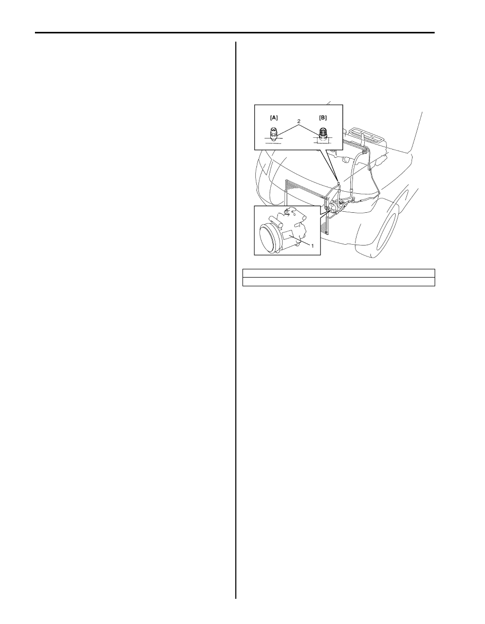
A/C Refrigerant Type Description
S5JB0A7201001
Whether the A/C in the vehicle being serviced uses
HFC-134a (R-134a) or CFC-12 (R-12) is indicated on
LABEL (1) on the compressor. Also, it can be checked
by the shape of the service (charge) valve (2).
[A]: HFC-134a (R-134a)
[B]: CFC-12 (R-12)
I5JB0A720005-01
Air Conditioning System: 7B-6
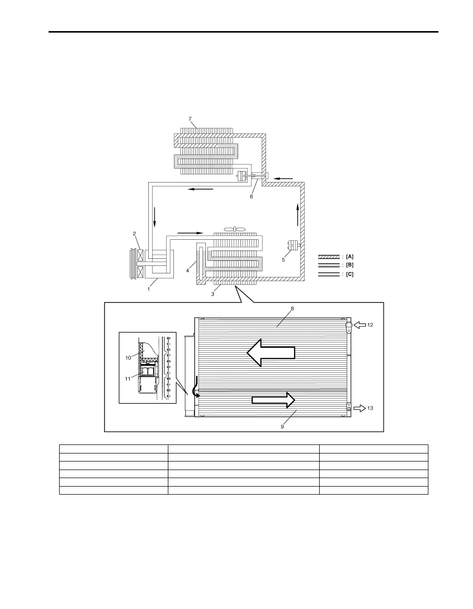
Sub-Cool A/C System Description
S5JB0A7201008
In the sub-cool A/C system (condenser (3) integrated with receiver / dryer (4)), the inside of the condenser is divided
into the condensation part and the sub-cooler part, and the receiver / dryer is located between those. In the receiver /
dryer (4), the refrigerant is separated into the vapor refrigerant and the liquid refrigerant. Only the liquid refrigerant is
delivered to the sub-cooler part of the condenser. The refrigerant is supercooled by the sub-cooler part of the
condenser.
I5JB0A720006-02
[A]: Liquid
4. Receiver / dryer
10. Desiccant
[B]: Vapor
5. Refrigerant pressure sensor
11. Filter
[C]: Superheated vapor
6. Expansion valve
12. Vapor refrigerant
1. Compressor
7. Evaporator
13. Liquid refrigerant
2. Magnet clutch
8. Condensation part
3. Condenser
9. Sub-cooler part
Нет комментариевНе стесняйтесь поделиться с нами вашим ценным мнением.
Текст