Suzuki Grand Vitara JB416 / JB420. Manual — part 297
7B-79 Air Conditioning System:
Magnet Clutch Removal and Installation for M16
Engine Model
S5JB0A7206048
Removal
1) Remove compressor from vehicle. Refer to
“Compressor Assembly Removal and Installation for
M16 Engine Model”.
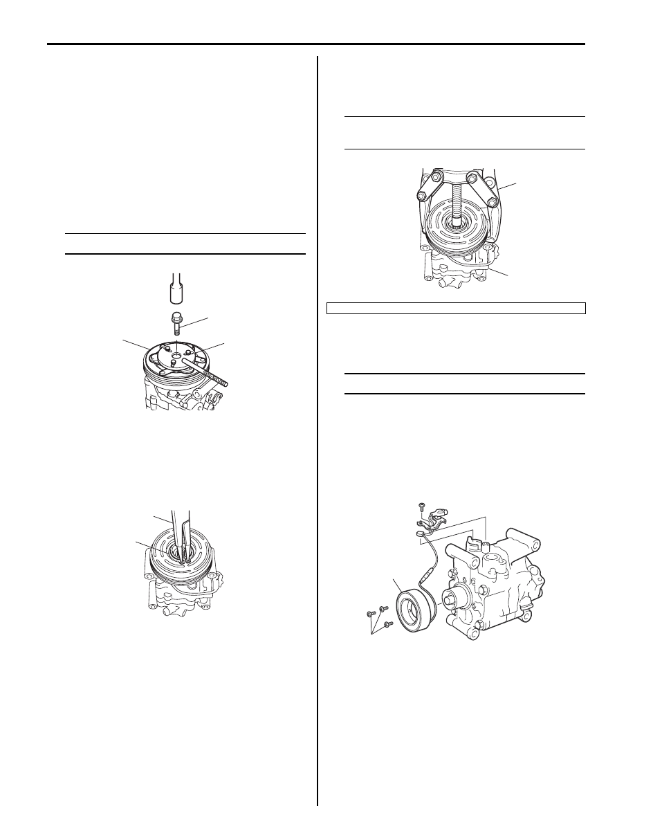
2) Fix armature plate (1) with special tool (A) and
remove armature plate bolt (2).
Special tool
(A): 09991–06310
NOTE
Do not reuse armature plate bolt.
3) Remove armature plate.
4) Remove shims from shaft.
5) Using special tool (A), remove circlip (1).
Special tool
(A): 09900–06107
6) Remove magnet clutch lead wire clamp screw, and
remove magnet clutch read wire ground terminal.
7) Remove magnet clutch pulley with puller (1).
NOTE
Be careful not to damage pulley when
tapping magnet clutch.
8) Remove magnet clutch bolts, and then remove
magnet clutch coil.
NOTE
Do not reuse magnet clutch bolts.
Installation
1) Install magnet clutch coil (2), and then tighten new
magnet clutch coil bolts (1) as specified torque.
Tightening torque
Magnet clutch coil bolt (a): 4.9 N·m (0.49 kgf-m,
4.0 lb-ft)
1
2
(A)
I5JB0A720064-02
(A)
1
I5JB0A720065-01
2. Compressor
1
2
I5JB0A720066-01
2
1, (a)
I5JB0A720067-02
Air Conditioning System: 7B-80
2) Install clamp portion and ground terminal of lead
wire.
3) Install magnet clutch pulley (1).
a) Set magnet clutch squarely over clutch
installation boss.
b) Place special tool (A) onto clutch bearing.
Ensure that edge rests only on inner race of
bearing.
Special tool
(A): 09951–15510
c) Install snap ring (1) using special tool (B).
Special tool
(B): 09900–06107
CAUTION
!
Be careful not to scratch bearing seal.
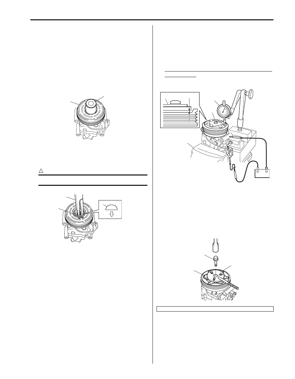
4) Inspect clearance between armature plate (1) and
magnet clutch pulley as follows.
a) Put compressor in a vise (2).
b) Set dial gauge (3) on armature plate, and then
adjust its pointer at 0.
c) Connect battery positive terminal (+) to magnet
clutch coil lead wire.
d) Connect battery negative terminal (–) to
compressor body assembly. (At this point,
armature plate and magnet clutch pulley are kept
in contact.)
e) Disconnect battery negative terminal (–) to
compressor body assembly. (At this point,
armature plate and magnet clutch pulley are not
in contact.)
f) Read stroke of armature plate from dial gauge by
performing Step d) and e) repeatedly. (Stroke of
armature plate is clearance between armature
plate and magnet clutch pulley.)
If clearance is out of specification, adjust
clearance by changing number and/or thickness
of shim(s).
Standard clearance between armature plate and
magnet clutch
“a”: 0.3 – 0.5 mm (0.012 – 0.020 in.)
5) Tighten new armature plate bolt (1) as specified
torque.
Tightening torque
Armature plate bolt (a): 15 N·m (1.5 kgf-m, 11.0
lb-ft)
Special tool
(A): 09991–06310
1
(A)
I5JB0A720068-02
(B)
1
1
I5JB0A720087-02
2. Armature plate
1
2
1
3
“a”
I5JB0A720069-01
2
1
(A)
I5JB0A720070-02
7B-81 Air Conditioning System:
Magnet Clutch Removal and Installation for J20
Engine Model
S5JB0A7206049
Removal
1) Remove compressor from vehicle referring to
“Compressor Assembly Removal and Installation for
J20 Engine Model”.
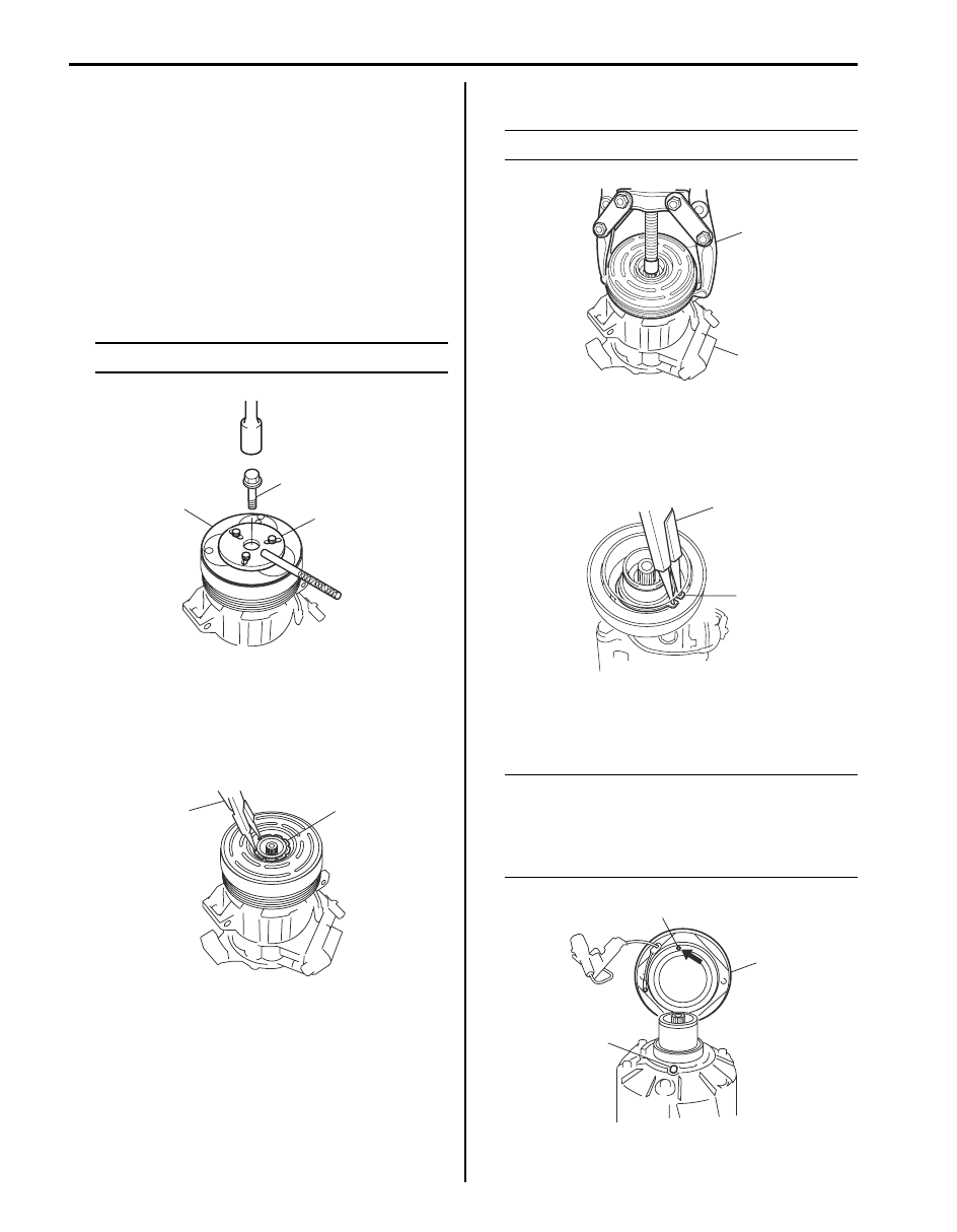
2) Fix armature plate (1) with special tool (A) and
remove armature plate bolt.
Special tool
(A): 09991–06310
NOTE
Do not reuse armature plate bolt.
3) Remove armature plate.
4) Remove shim(s) from shaft.
5) Using special tool (A), remove snap ring (1).
Special tool
(A): 09900–06107
6) Remove magnet clutch pulley (1) with puller (2).
NOTE
Be careful not to damage pulley.
7) Remove snap ring (1) using special tool (B), and
then remove magnet clutch coil (1).
Special tool
(A): 09900–06107
Installation
1) Install magnet clutch coil (3).
NOTE
Protrusion (1) on underside of magnet clutch
coil and hole (2) on compressor body
assembly must match to stop movement of
magnet clutch coil and to locate lead wire
correctly.
1
(A)
2
I5JB0A720071-01
(A)
1
I5JB0A720072-01
1
2
I5JB0A720073-01
(A)
1
I5JB0A720074-02
2
1
3
I5JB0A720075-01
Air Conditioning System: 7B-82
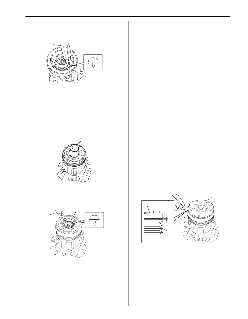
2) Install new snap ring (1) using special tool (A).
Special tool
(B): 09900–06107
3) Install magnet clutch pulley.
a) Set magnet clutch horizontally over clutch
installation boss.
b) Place special tool (B) onto magnet clutch
bearing. Ensure that edge rests only inner rase
of bearing.
Special tool
(B): 09951–15510
c) Install new snap ring (1) using special tool (A).
Special tool
(A): 09900–06107
4) Install armature plate (1).
5) Using special tool (A), tighten new armature plate
bolt (2) to specified torque.
Tightening torque
Armature plate bolt (a): 21 N·m (2.1 kgf-m, 15.5
lb-ft)
Special tool
(A): 09991–06310
6) Adjust clearance between armature plate (1) and
magnet clutch pulley by putting shim(s) on
compressor shaft. To measure the clearance,
perform the following steps.
a) Put compressor in a vise.
b) Set dial gauge on magnet clutch plate, and then
adjust its pointer at 0.
c) Connect battery positive terminal (+) to magnet
clutch coil lead wire.
d) Connect battery negative terminal (–) to
compressor body assembly. (At this point,
armature plate and magnet clutch pulley (2) are
kept in contact.)
e) Disconnect battery negative terminal (–) to
compressor body assembly. (At this point,
armature plate and magnet clutch pulley (2) are
not in contact.)
f) Read stroke of armature plate from dial gauge by
performing Step d) and e) repeatedly. (Stroke of
armature plate is clearance between armature
plate and magnet clutch pulley (2).)
Standard clearance between armature plate and
magnet clutch
“a”: 0.3 – 0.6 mm (0.012 – 0.024 in.)
7) Install compressor to vehicle referring to
“Compressor Assembly Removal and Installation for
J20 Engine Model”.
(A)
1
1
I5JB0A720088-04
(B)
I5JB0A720076-02
(A)
1
1
I5JB0A720077-01
1
2
2
1
“a”
I5JB0A720078-02
Нет комментариевНе стесняйтесь поделиться с нами вашим ценным мнением.
Текст