Suzuki Grand Vitara JB416 / JB420. Manual — part 244
5A-110 Automatic Transmission/Transaxle:
Overdrive (Case Side) Disassembly and
Assembly
S5JB0A5106075
Disassembly
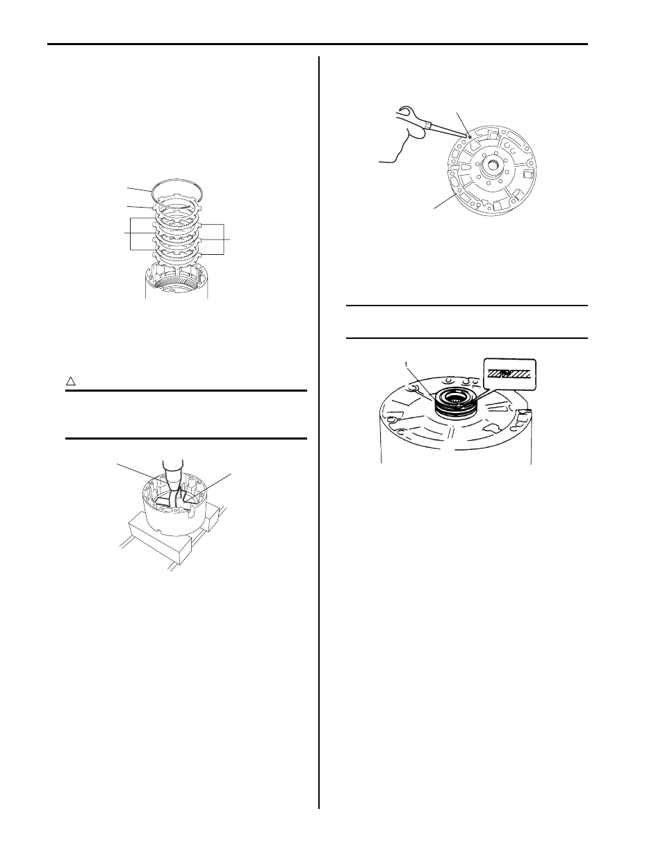
1) Remove retaining ring (1), brake backing plate (2),
brake disc (3) and brake plate (4) in that order. Then
remove planetary ring gear, thrust bearing race and
thrust bearing.
2) Remove retaining ring and piston return spring using
special tool and press (1).
Special tool
(A): 09926–96510
CAUTION
!
Be careful when applying pressure, for
overpressure will cause plate section of
piston return spring to deform.
3) Apply compressed air (400 – 800 kPa, 4 – 8 kg/cm
2
,
57 – 113 psi) to oil hole (1) in O/D case (2) and
remove brake piston.
4) Remove brake piston inner ring and brake piston
outer ring from brake piston.
5) Unsnap seal ring (1).
6) Remove 2 seal rings (1).
NOTE
Be careful not to open seal ring more than
necessary.
1
2
3
4
I5JB0A510104-01
1
(A)
I5JB0A510105-01
1
2
I5JB0A510106-01
IYSQ01510138-01
Automatic Transmission/Transaxle: 5A-111
Assembly
Install each component by reversing removal procedure
and noting the following points.
• When installing rear seal ring, use care not to open it
too wide.
• Apply A/T fluid to O-ring, disc, etc. before installing
them.
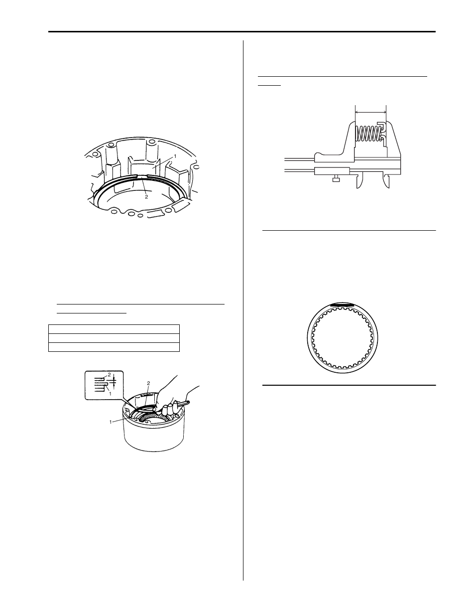
• Opening of retaining brake front ring (2) and
projection (1) of O/D case should be matched.
• When installing each component, refer to “Overdrive
• Measure clearance between retaining ring (1) and
brake backing plate (2) with thickness gauge.
If the clearance is out of specification, select another
plate with suitable thickness from the list below and
replace it.
Standard clearance between retaining ring and
brake backing plate
0.40 – 1.38 mm (0.016 – 0.054 in.)
Overdrive (Case Side) Inspection
S5JB0A5106076
• Measure free length of piston return spring.
Standard free length of O/D brake piston return
spring
15.10 mm (0.594 in.)
• Check that sliding surface of discs and plate are not
worn or burnt. If necessary, replace them.
NOTE
• If disc lining is exfoliated, discolored or
worn hardly, replace all discs.
• If only a part of printed numbers is
corroded, replace all discs.
• Before assembling new discs, soak them
in A/T fluid for at least 15 minutes.
Thickness
1.95 – 2.05 mm (0.077 – 0.081 in.)
2.25 – 2.35 mm (0.089 – 0.093 in.)
IYSQ01510139-01
IYSQ01510134-01
I5JB0A510171-01
I4JA01512210-01
5A-112 Automatic Transmission/Transaxle:
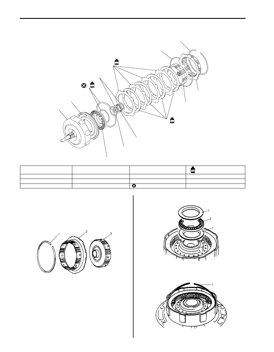
Forward Clutch Components
S5JB0A5106077
Forward Clutch Disassembly and Assembly
S5JB0A5106078
Disassembly
1) After removing retaining ring (1), remove direct
clutch hub (2) and forward clutch hub (3).
2) Remove bearing race (1) and thrust bearing (2).
3) Remove retaining ring (1) and then remove all clutch
discs.
1
2
3
4
5
5
5
6
7
8
9
10
11
FLD
FLD
FLD
I5JB0A510108-01
1. Input shaft
5. Retaining ring
9. Clutch disc
: Apply A/T fluid.
2. Piston
6. Bearing race
10. Froward clutch hub
3. Return spring
7. Bearing
11. Direct clutch hub
4. O-ring
8. Clutch plate
: Do not reuse.
IYSQ01510143-01
I5JB0A510109-01
IYSQ01510147-01
Automatic Transmission/Transaxle: 5A-113
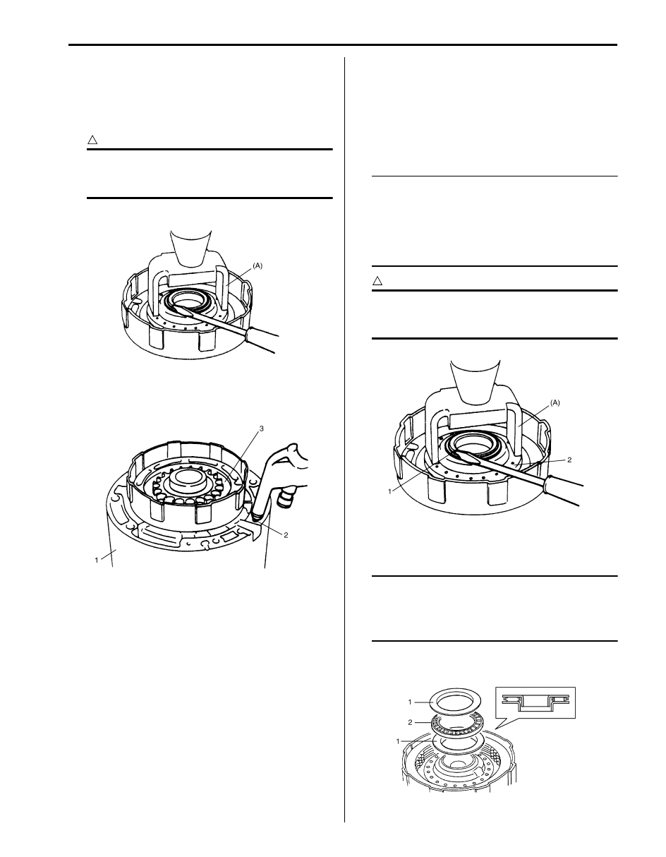
4) Using special tool and hydraulic press, compress
forward clutch piston return spring and remove
retaining return spring.
Special tool
(A): 09926–98310
CAUTION
!
Be careful when applying pressure, for
overpressure will cause plate section of
piston return spring to deform.
5) Remove forward clutch piston return spring.
6) Install forward clutch to O/D case (1). Blow low
pressure air into fluid hole (2) at the right of cut in O/
D case to remove forward clutch piston (3).
Assembly
1) Apply A/T fluid to forward input shaft O-rings, install
forward clutch piston and piston return spring (2) to
forward input shaft and then install return spring ring
with special tool and hydraulic press.
Special tool
(A): 09926–98310
NOTE
• When installing return spring (2), be
careful so that return spring will not fall or
tilt.
• Do not align opening in retaining ring (1)
with lug of forward clutch piston return
spring at its retainer section.
CAUTION
!
Be careful when applying pressure, for
overpressure will cause plate section of
piston return spring to deform.
2) Install clutch discs and plates and then install
retaining clutch ring.
NOTE
• Refer to “Forward Clutch Components”
when installing each component.
• Do not match opening in retaining clutch
ring and dent in forward clutch input shaft.
3) Install bearing races (1) and thrust bearing (2).
IYSQ01510148-01
I5JB0A510110-01
IYSQ01510150-01
I5JB0A510111-01
Нет комментариевНе стесняйтесь поделиться с нами вашим ценным мнением.
Текст