Suzuki Grand Vitara JB416 / JB420. Manual — part 242

5A-102 Automatic Transmission/Transaxle:
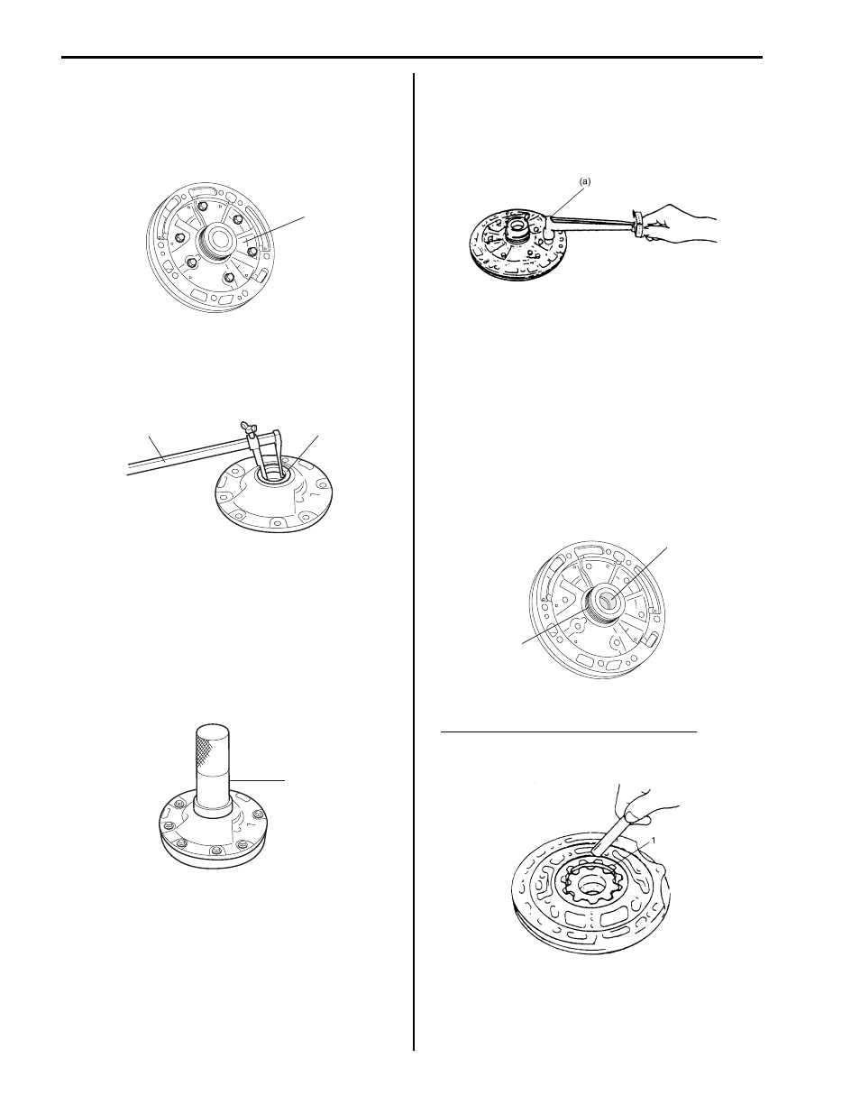
33) Remove manual shift shaft and lever as follows.
a) Undo caulking of sleeve cover (1) by using flat
end rod or the like and hammer.
b) Drive out manual shift lever pin (1) by using
special tool and hammer.
Special tool
(A): 09922–89810
c) Pull out manual shift shaft (2) from transmission
case, and then remove manual shift lever (3) and
sleeve cover (4).
34) Remove oil seal (1) from both sides of transmission
case.
35) Remove cover plate (1).
1
I4JA01512082-01
1
3
(A)
2
4
I4JA01512083-01
IYSQ01510111-01
1
I5JB0A510089-01

Automatic Transmission/Transaxle: 5A-103
Oil Pump Components
S5JB0A5106068
4
6
FLD
2
1
FLD
3
5
(a)
I5JB0A510090-01
1. Oil pump body oil seal
4. Seal ring
: 7.5 N
⋅m (0.75 kgf-m, 5.5 lb-ft)
2. Oil pump cover O-ring
5. Oil pump body
: Do not reuse.
3. Oil pump cover
6. Oil pump bolt
: Apply A/T fluid.
5A-104 Automatic Transmission/Transaxle:
Oil Pump Disassembly and Assembly
S5JB0A5106069
Disassembly
1) Remove 6 bolts, oil pump cover (1), drive gear and
driven gear in that order.
2) Remove oil pump cover O-ring.
3) Remove oil pump body oil seal (1) using special tool.
Special tool
(A): 09913–50121
Assembly
Assemble each component by reversing removal
procedure and noting the following points.
• Before installing inner gear and outer gear to pump
body, apply A/T fluid to them.
• Install oil pump seal using special tool.
Special tool
(A): 09913–85210
• When installing pump cover, use care so that its
splined part will not cause damage to oil seal and use
specified torque to tighten it to pump body.
Tightening torque
Oil pump bolt (a): 7.5 N·m (0.75 kgf-m, 5.5 lb-ft)
• When installing O-ring and oil seal, apply enough A/T
fluid to them and fit them securely in groove.
• After installation, check that inner gear turns smoothly
by making use of torque converter.
• When installing seal ring, it should not be opened
more than necessary.
• Fit claws of seal ring securely.
Oil Pump Inspection
S5JB0A5106070
• Check seal ring (2) and bushing (1) for wear and
damage.
• Check clearance between outer gear (1) and body.
Clearance between outer gear and body
Standard: 0.07 – 0.15 mm (0.0028 – 0.0059 in.)
Service limit: 0.30 mm (0.0118 in.)
1
I5JB0A510091-01
1
(A)
I5JB0A510093-01
(A)
I5JB0A510092-01
IYSQ01510114-01
1
2
I5JB0A510094-01
IYSQ01510116-01

Automatic Transmission/Transaxle: 5A-105
• Check tip clearance between inner gear (1) and outer
gear.
Tip clearance between inner gear and outer gear
Standard: 0.11 – 0.14 mm (0.0043 – 0.0055 in.)
Service limit: 0.30 mm (0.0118 in.)
NOTE
Measure with torque converter installed.
• Check side clearance between inner gear/outer gear
and pump body.
Side clearance between inner gear / outer gear
and pump body
Standard: 0.02 – 0.05 mm (0.0008 – 0.0020 in.)
Service limit: 0.1 mm (0.0039 in.)
• Measure inside diameter of oil pump body bushing.
If inside diameter exceeds limit, replace oil pump
body.
Oil pump body bushing inside diameter standard
38.113 – 38.138 mm (1.5005 – 1.5014 in.)
• Measure inside diameter of stator shaft assembly
bushing.
If inside diameter exceeds limit, replace stator shaft
assembly.
Stator shaft assembly bushing inside diameter
standard
Front side (2): 21.501 – 21.527 mm (0.8465 – 0.8475
in.)
Rear side (1): 23.025 – 23.051 mm (0.9065 – 0.9075
in.)
IYSQ01510117-01
IYSQ01510118-01
I4JA01512140-01
I5JB0A510148-01
Нет комментариевНе стесняйтесь поделиться с нами вашим ценным мнением.
Текст