Suzuki Grand Vitara JB416 / JB420. Manual — part 127
1G-10 Fuel System:
Fuel Pressure Relief Procedure
S5JB0A1706002
CAUTION
!
This work must not be done when engine is
hot. If done so, it may cause adverse effect to
catalyst.
NOTE
If ECM detects DTC(s) after servicing, clear
DTC(s) referring to “DTC Clearance in
Section 1A”.
1) Make sure that engine is cold.
2) Shift transaxle gear shift lever in “Neutral” (shift
select lever in “P” range for A/T model), set parking
brake and block drive wheels.
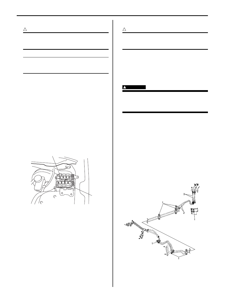
3) Remove fuse box No.2 cover.
4) Disconnect fuel pump relay (1) from fuse box No.2
(2).
5) Remove fuel filter cap in order to release fuel vapor
pressure in fuel tank, and then reinstall it.
6) Start engine and run it until engine stops for lack of
fuel. Repeat cranking engine 2 – 3 times for about 3
seconds each time in order to dissipate fuel pressure
in lines. Fuel connections are now safe for servicing.
7) After servicing, connect fuel pump relay (1) to fuse
box No.2 and install fuse box No.2 cover.
Fuel Leakage Check Procedure
S5JB0A1706003
After performing any service on fuel system, check to
make sure that there are no fuel leakages as follows.
1) Turn ON ignition switch for 3 seconds (to operate
fuel pump) and then turn it OFF.
Repeat this (ON and OFF) 3 or 4 times and apply
fuel pressure to fuel line until fuel pressure is felt by
hand placed on fuel feed hose.
2) In this state, check to see that there are no fuel
leakages from any part of fuel system.
Fuel Lines On-Vehicle Inspection
S5JB0A1706004
CAUTION
!
Due to the fact that fuel feed line (1) is under
high pressure, use special care when
servicing it.
Visually inspect fuel lines for evidence of fuel leakage,
hose crack and deterioration or damage.
Make sure all clamps are secure.
Replace parts as needed.
Fuel Pipe Removal and Installation
S5JB0A1706005
WARNING
!
Before starting the following procedure, be
sure to observe “Precautions on Fuel System
Service” in order to reduce the risk or fire
and personal injury.
Removal
1) Relieve fuel pressure in fuel feed line according to
“Fuel Pressure Relief Procedure”.
2) Disconnect negative cable at battery.
3) Disconnect fuel pipe joint and fuel hose (3) from fuel
pipe (2) at the front and rear of each fuel pipe
referring to “Fuel Hose Disconnecting and
Reconnecting”.
4) Mark the location of clamps (1) on fuel pipes (2), so
that the clamps can be reinstalled to where they
were.
5) Remove pipes (2) with clamp (1) from vehicle.
6) Remove clamp (1) from pipes (2).
1
2
I5JB0A171006-01
I5JB0A170006-03
Fuel System: 1G-11
Installation
1) Install clamps to marked
®® location on pipes. If
clamp is deformed, its claw is bent or broken,
replace it with new one.
2) Install pipes with pipe clamps to vehicle.
NOTE
For M16 engine model, be sure to tighten fuel
pipe bolt as specified tightening order
described in “Fuel System Components”.
3) Connect fuel hoses and pipes to each pipe referring
to “Fuel Hose Disconnecting and Reconnecting”.
4) Connect negative cable at battery.
5) With engine OFF, turn ignition switch to ON position
and check for fuel leaks.
Fuel Injector On-Vehicle Inspection
S5JB0A1706006
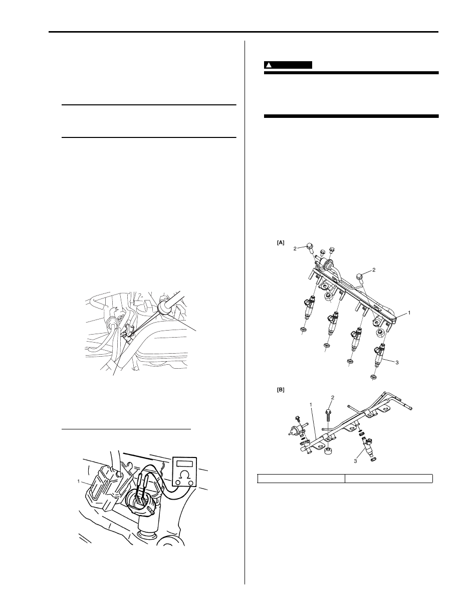
1) Using sound scope (1) or such, check operating
sound of injector (2) when engine is running or
cranking.
Cycle of operating sound should vary according to
engine speed.
If no sound or an unusual sound is heard, check
injector circuit (wire or coupler) or injector.
2) Disconnect connector (1) from injector, connect
ohmmeter between terminals of injector and check
resistance.
Reference resistance of fuel injector
12
Ω at 20 °C, 68 °F
3) Connect connector to injector securely.
Fuel Injector Removal and Installation
S5JB0A1706007
WARNING
!
Before starting the following procedure, be
sure to observe “Precautions on Fuel System
Service” in order to reduce the risk or fire
and personal injury.
Removal
1) Relieve fuel pressure according to “Fuel Pressure
2) Disconnect negative cable at battery.
3) Disconnect fuel injector couplers.
4) Disconnect fuel feed hose from fuel delivery pipe (1).
5) Disconnect fuel return hose from pressure regulator.
6) Disconnect vacuum hose from pressure regulator.
7) Remove fuel delivery pipe bolts (2).
8) Remove fuel injector(s) (3).
1
2
I5JB0A171007-01
I2RH0B170008-01
[A]: For M16 engine model
[B]: For J20 engine model
I5JB0A170007-02
1G-12 Fuel System:
Installation
Reverse removal procedure for installation noting the
following.
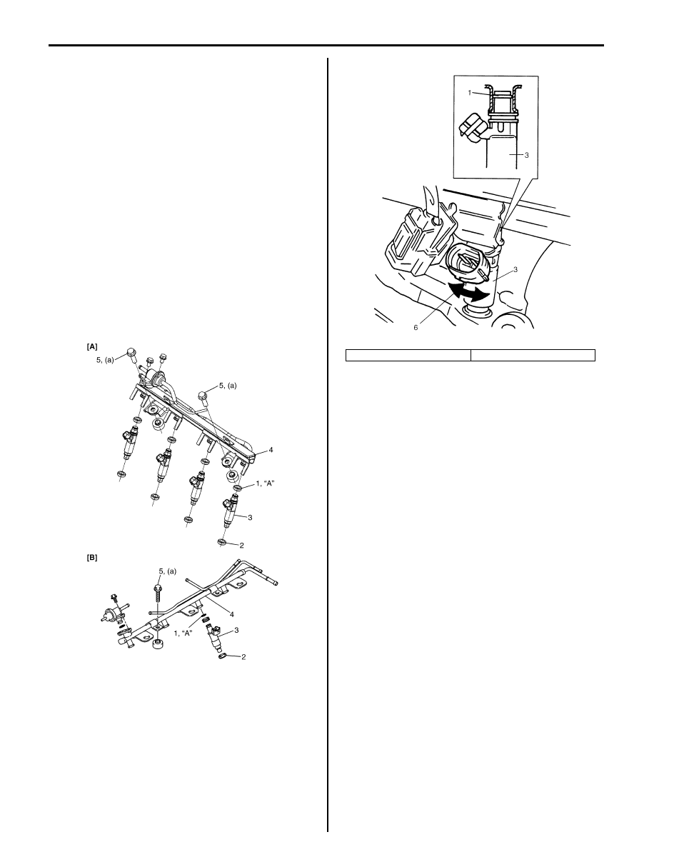
• Replace injector O-ring (1) with new one using care
not to damage it.
• Check if cushion (2) is scored or damaged. If it is,
replace with new one.
• Apply O-ring oil to O-rings (1), and then install
injectors (3) into delivery pipe (4) and cylinder head.
Make sure that injectors rotate smoothly (6). If not,
probable cause is incorrect installation of O-ring.
Replace O-ring with new one.
“A”: Oil 99000–25320 (SUZUKI DI O RING
OIL(500CC))
• Tighten delivery pipe bolts (5) to specified torque and
make sure that injectors rotate smoothly.
Tightening torque
Fuel delivery pipe bolt (a): 25 N·m (2.5 kgf-m, 18.0
lb-ft)
• After installation, with engine OFF and ignition switch
ON, check for fuel leaks around fuel line connection.
I5JB0A170008-02
[A]: For M16 engine model
[B]: For J20 engine model
I5JB0A171008-02

Fuel System: 1G-13
Fuel Injector Inspection
S5JB0A1706008
WARNING
!
Before starting the following procedure, be
sure to observe “Precautions on Fuel System
Service” in order to reduce the risk or fire
and personal injury.
1) Install injector to special tool (injector checking tool).
2) Install pressure regulator to special tool (injector
checking tool).
Special tool
(A): 09912–58421
(B): 09912–58442
3) Connect special tools (hose and attachment) to fuel
feed pipe (1) of vehicle.
4) Connect special tool (test lead) to injector.
Special tool
(C): 09930–88530
5) Install suitable vinyl tube onto injector nozzle to
prevent fuel from splashing out when injecting.
6) Put graduated cylinder under injector.
7) Operate fuel pump and apply fuel pressure to
injector as follows:
a) When using scan tool:
i)
Connect scan tool to DLC with ignition switch
OFF.
ii) Turn ignition switch ON, clear DTC and
select “MISC TEST” mode on scan tool.
iii) Turn fuel pump ON by using scan tool.
Special tool
(A): SUZUKI scan tool
b) When not using scan tool:
i)
Remove fuel pump relay from connector.
ii) Connect two terminals of relay connector
using service wire (1) as shown in the figure.
CAUTION
!
Check to make sure that connection is made
between correct terminals. Wrong
connection can cause damage to ECM, wire
harness, etc.
A
B
C
1
A
I5JB0A170004-02
(A)
I5JB0A171009-01
Нет комментариевНе стесняйтесь поделиться с нами вашим ценным мнением.
Текст