Suzuki Grand Vitara JB416 / JB420. Manual — part 212

4E-25 ABS:
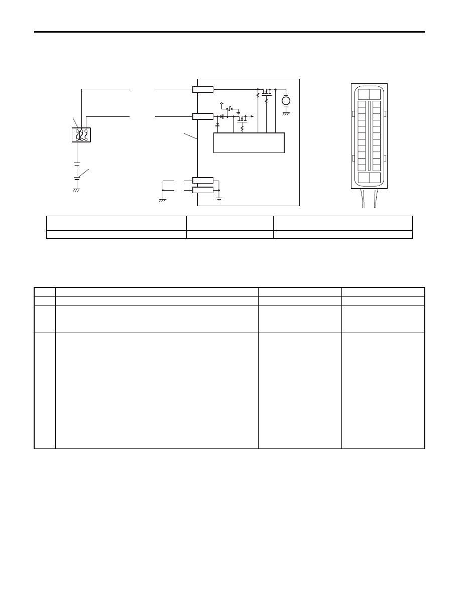
DTC C1061: ABS Pump Motor and/or Motor Driver Circuit
S5JB0A4504016
Wiring Diagram
DTC Detecting Condition
The ABS control module monitors the voltage at monitor terminal of pump motor circuit constantly with the ignition
switch turned ON. It sets this DTC when the voltage at the monitor terminal does not become high / low according to
ON/OFF commands to the motor driver (transistor) of the module (does not follow these commands).
DTC Troubleshooting
5
1) Measure voltage between terminals “E03-14” and “E03-
13” with engine running.
Is voltage 18
±
1.0 V or less?
Poor connection of
“E03-14” and/or “E03-
13” terminals. If the
terminals are in good
condition, substitute a
known-good ABS
hydraulic unit / control
module and recheck.
Check charging system
referring to “Generator
Test (Overcharged
Battery Check) in
Section 1J”.
Step
Action
Yes
No
4
5
1
2
WHT/BLU
3
12V
M
12V
BLK
BLK
E03-13
E03-26
E03-1
[A]
E03
15
16
17
18
19
20
21
22
23
24
25
2
3
4
5
6
7
8
9
10
11
12
1
13
14
26
I5JB0A450017-02
[A]: ABS hydraulic unit / control module connector
(viewed from terminal side)
2. Main fuse box
4. ABS pump motor
1. Battery
3. Pump motor driver (transistor)
5. ABS hydraulic unit / control module assembly
Step
Action
Yes
No
1
Was “ABS Check” performed?
Go to Step 2.
2
1) Turn Ignition switch to OFF position.
2) Disconnect ABS hydraulic unit / control module
connector.
3) Check for proper connection to ABS hydraulic unit /
control module connector at terminal “E03-1”.
4) If OK, then measure voltage between terminal “E03-1” of
module connector and body ground.
Is it 10 – 14 V?
Go to Step 3.
“WHT/BLU” circuit
open.
3
Measure resistance between terminal “E03-13” and “E03-
26” of ABS hydraulic unit / control module connector and
vehicle body ground.
Is resistance less than 1
Ω
?
Substitute a known-
good ABS hydraulic unit
/ control module
assembly and recheck.
Ground circuit for ABS
hydraulic unit / control
module open or high
resistance.

ABS: 4E-26
DTC C1063: Solenoid Valve Power Supply Driver Circuit
S5JB0A4504017
Wiring Diagram
DTC Detecting Condition
ABS control module monitors the voltage at the terminal of solenoid circuit constantly with ignition switch turned ON.
Also, immediately after ignition switch is turned ON, perform initial check as follows.
Switch solenoid valve power supply driver (transistor) in the order of OFF
→ ON and check if voltage changes to Low
→ High. If anything faulty is found in the initial check and when the voltage is low with ignition switch turned ON, this
DTC will be set.
DTC Troubleshooting
3
4
12V
GRN/ORN
BLK/YEL
5
5V
12V
WHT/GRN
E03-7
E03-14
WHT/RED
[A]
E03
6
8
7
1
2
15
16
17
18
19
20
21
22
23
24
25
2
3
4
5
6
7
8
9
10
11
12
1
13
14
26
I5JB0A450018-02
[A]: ABS hydraulic unit / control module connector
(viewed from terminal side)
5. Solenoid valve power supply driver (transistor)
1. Battery
6. ABS hydraulic unit / control module assembly
2. Main fuse box
7. To solenoid valve
3. Ignition switch
8. ABS power control module
4. Circuit fuse box (in junction block assembly)
Step
Action
Yes
No
1
Was “ABS Check” performed?
Go to Step 2.
2
Check battery voltage.
Is it about 11 V or higher?
Go to Step 3.
Check charging system
referring to “Battery
Inspection in Section
1J” and “Generator Test
(Undercharged Battery
Check) in Section 1J”.
3
Check main fuse for ABS solenoid and its terminal.
Is it in good condition?
Go to Step 4.
Replace fuse and check
for short circuit to
ground.
4
1) Turn ignition switch to OFF position.
2) Disconnect ABS hydraulic unit / control module
connector.
3) Check for proper connection to ABS hydraulic unit /
control module at terminal “E03-14”.
4) If OK, then measure voltage between connector terminal
“E03-14” and body ground.
Is it 10 – 14 V?
Substitute a known-
good ABS hydraulic unit
/ control module
assembly and recheck.
“WHT/BLU” circuit
imperfect short to
ground.
4E-27 ABS:
DTC C1071: ABS Control Module
S5JB0A4504018
Wiring Diagram
DTC Detecting Condition
This DTC will be set when an internal malfunction is detected in the ABS control module.
DTC Troubleshooting
1
2
WHT/BLU
12V
M
3
4
E03-1
E03-14
BLK
BLK
E03-13
E03-26
WHT/RED
[A]
E03
15
16
17
18
19
20
21
22
23
24
25
2
3
4
5
6
7
8
9
10
11
12
1
13
14
26
I5JB0A450019-02
[A]: ABS hydraulic unit / control module connector
(viewed from terminal side)
2. Main fuse box
4. ABS hydraulic unit / control module assembly
1. Battery
3. ABS power control module
Step
Action
Yes
No
1
Was “ABS Check” performed?
Go to Step 2.
2
Clear all DTCs and check DTC.
Is it DTC C1071?
Go to Step 3.
Could be a temporary
malfunction of the ABS
control module.
3
1) Check for proper connection of ABS hydraulic unit /
control module connector.
2) If OK, disconnect ABS hydraulic unit / control module
connector and check the following.
• Voltage “E03-1” terminal: 10 – 14 V
• Voltage “E03-14” terminal: 10 – 14 V
• Resistance between “E03-13” and body ground:
Continuity
• Resistance between “E03-26” and body ground:
Continuity
Are the check result as specified?
Replace ABS hydraulic
unit / control module
assembly.
Repair “WHT/RED”,
“WHT/BLU” and/or
“BLK” circuit and
recheck.
ABS: 4E-28
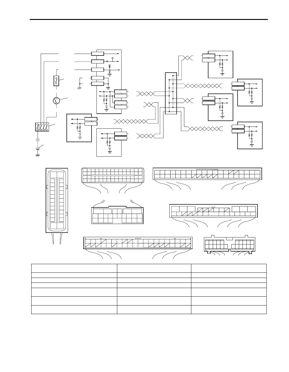
DTC U1073: Control Module Communication Bus Off
S5JB0A4504020
Wiring Diagram
DTC Detecting Condition
Transmission error that is inconsistent between transmission data and transmission monitor (CAN bus monitor) data is
detected more than 7 times continuously.
WHT
RED
WHT
RED
WHT/BLU
WHT/RED
WHT
RED
WHT
RED
E92-17
E92-7
E03-12
E03-6
E03-10
E03-8
12V
12V
E03-1
E03-14
E03-7
E03-13
E03-26
GRN/ORN
BLK/YEL
WHT/GRN
WHT/RED
WHT/BLU
[A]
[D]
WHT/BLU
WHT/RED
E23-19
E23-4
E91-22
E91-23
WHT
RED
WHT
RED
BLK
BLK
E03
G31-1
G31-3
[B]
[C]
[G]
[F]
G44
1
2
3
4
5
6
7
8
9
10
11
14
15
16
36
34 33 32 31 30 29
24 23
37
18
19
20
6
5
16 15 14 13 12 11
4 3
24 23
21
22
10 9
8
7
2
1
19
20
18 17
E92
2 1
E23
3
4
18
19
5
6
7
10
11
17
20
47 46
49
50
51
21
22
52
16
25
9
24
14
29
55
57
5453
59
60
58
26
27
28
15
30
56
48
32 31
34
35
36
37
40
42
3938
44
45
43
41
33
12
13
23
8
1
2
3
4
5
6
7
8
9
10
11
17
1615141312
2221201918
G28
G31
1
2
3
4
7
8
9
10
11
14
15
16
36
34
35
24 23
21
22
28 27
25
26
37
39 38
40
18 17
13 12
19
20
E91
1
2
3
10
11
12
16
17
18
15 14 13
19
20
21
25
26
5
6
[E]
G44-18
G44-19
G28-10
G28-8
6
7
1
2
3
4
5
12
8
9
10
11
15
16
17
18
19
20
21
22
23
24
25
2
3
4
5
6
7
8
9
10
11
12
1
13
14
26
I5JB0A450020-02
[A]: ABS hydraulic unit / control module connector
(viewed from terminal side)
1. Battery
8. TCM (for A/T model)
[B]: ECM connector (viewed from harness side)
2. Main fuse box
9. 4WD control module (if equipped)
[C]: BCM connector (viewed from harness side)
3. Ignition switch
10. Keyless start control module (if equipped)
[D]: TCM connector (viewed from harness side)
4. Circuit fuse (in junction block assembly)
11. Combination meter
[E]: 4WD control module connector
(viewed from harness side)
5. ABS hydraulic unit / control module
assembly
12. CAN junction
[F]: Keyless start control module connector
(viewed from harness side)
6. ECM
[G]: Combination meter connector (viewed from
harness side)
7. BCM
Нет комментариевНе стесняйтесь поделиться с нами вашим ценным мнением.
Текст