Suzuki Grand Vitara JB416 / JB420. Manual — part 121
1E-20 Engine Lubrication System: For J20 Engine
Special Tools and Equipment
Recommended Service Material
S5JB0A1528001
NOTE
Required service material is also described in the following.
“Oil Pan and Oil Pump Strainer Components: For J20 Engine”
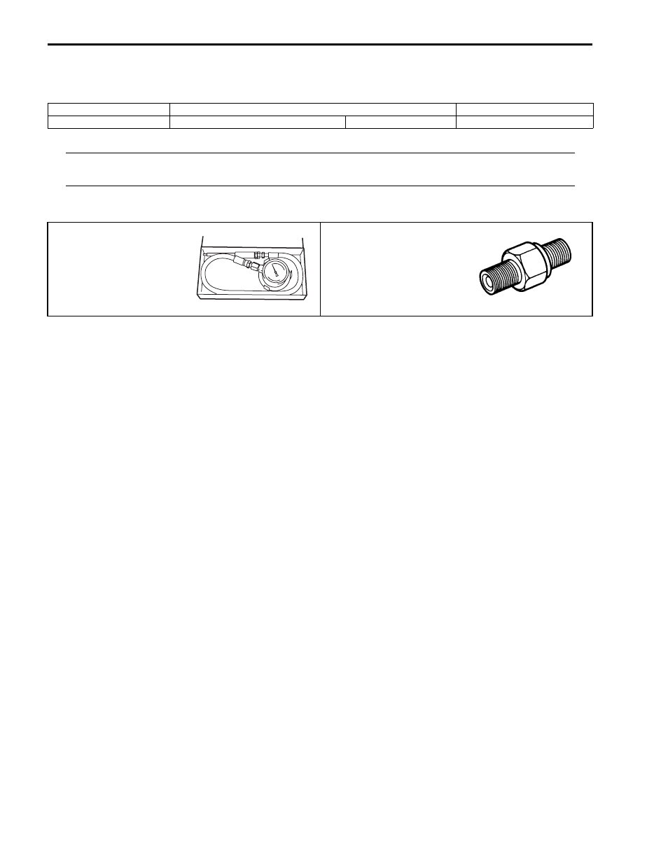
Special Tool
S5JB0A1528002
Material
SUZUKI recommended product or Specification
Note
Water tight sealant
SUZUKI Bond No.1207F
P/No.: 99000–31250
09915–77311
09915–78211
Oil pressure gauge
Oil pressure gauge
attachment
Engine Cooling System: 1F-1
Engine
Engine Cooling System
General Description
Cooling System Description
S5JB0A1601001
The cooling system consists of the radiator cap, radiator,
coolant reservoir, hoses, water pump, cooling fan and
thermostat. The radiator is of tube-and-fin type.
Coolant Description
S5JB0A1601002
WARNING
!
• Do not remove radiator cap to check
engine coolant level; check coolant
visually at the see-through coolant
reservoir. Coolant should be added only to
reservoir as necessary.
• As long as there is pressure in the cooling
system, the temperature can be
considerably higher than the boiling
temperature of the solution in the radiator
without causing the solution to boil.
Removal of the radiator cap while engine is
hot and pressure is high will cause the
solution to boil instantaneously and
possibly with explosive force, spewing the
solution over engine, fenders and person
removing cap. If the solution contains
flammable anti-freeze such as alcohol (not
recommended for use at any time), there is
also the possibility of causing a serious
fire.
• Check to make sure that engine coolant
temperature is cold before removing any
part of cooling system.
• Also be sure to disconnect negative cable
from battery terminal before removing any
part.
The coolant recovery system is standard. The coolant in
the radiator expands with heat, and the coolant is
overflowed to the reservoir.
When the system cools down, the coolant is drawn back
into the radiator.
The cooling system has been filled with a quality coolant
that is a 50/50 mixture of water and ethylene glycol
antifreeze.
This 50/50 mixture coolant solution provides freezing
protection to –36
°C (–33 °F).
• Maintain cooling system freeze protection at –36
°C (–
33
°F) to ensure protection against corrosion and loss
of coolant from boiling. This should be done even if
freezing temperatures are not expected.
• Add ethylene glycol base coolant when coolant has to
be added because of coolant loss or to provide added
protection against freezing at temperature lower than
–36
°C (–33 °F).
NOTE
• Alcohol or methanol base coolant or plain
water alone should not be used in cooling
system at any time as damage to cooling
system could occur.
• Coolant must be mixed with deminerated
water or distilled water.
Anti-freeze proportioning table
Coolant capacity (M16 Engine)
Engine, radiator and heater: 6.1 liters (12.89/10.74
US/lmp pt.)
Reservoir: 0.8 liters (1.69/1.40 US/lmp pt.)
Total: 6.9 liters (14.58/12.14 US/lmp pt.)
Coolant capacity (J20 Engine)
Engine, radiator and heater: 6.6 liters (13.95/11.62
US/lmp pt.)
Reservoir: 0.7 liters (1.48/1.23 US/lmp pt.)
Total: 7.3 liters (15.42/12.85 US/lmp pt.)
For M16
engine
model
For J20
engine
model
Freezing temperature
°C
–36
–36
°F
–33
–33
Anti-freeze / Anti-
corrosion coolant
concentration
%
50
50
Ratio of compound to
cooling water
ltr.
3.45/3.45 3.65/3.65
US pt.
7.29/7.29 7.71/7.71
Imp pt. 6.07/6.07 6.42/6.42
1F-2 Engine Cooling System:
Schematic and Routing Diagram
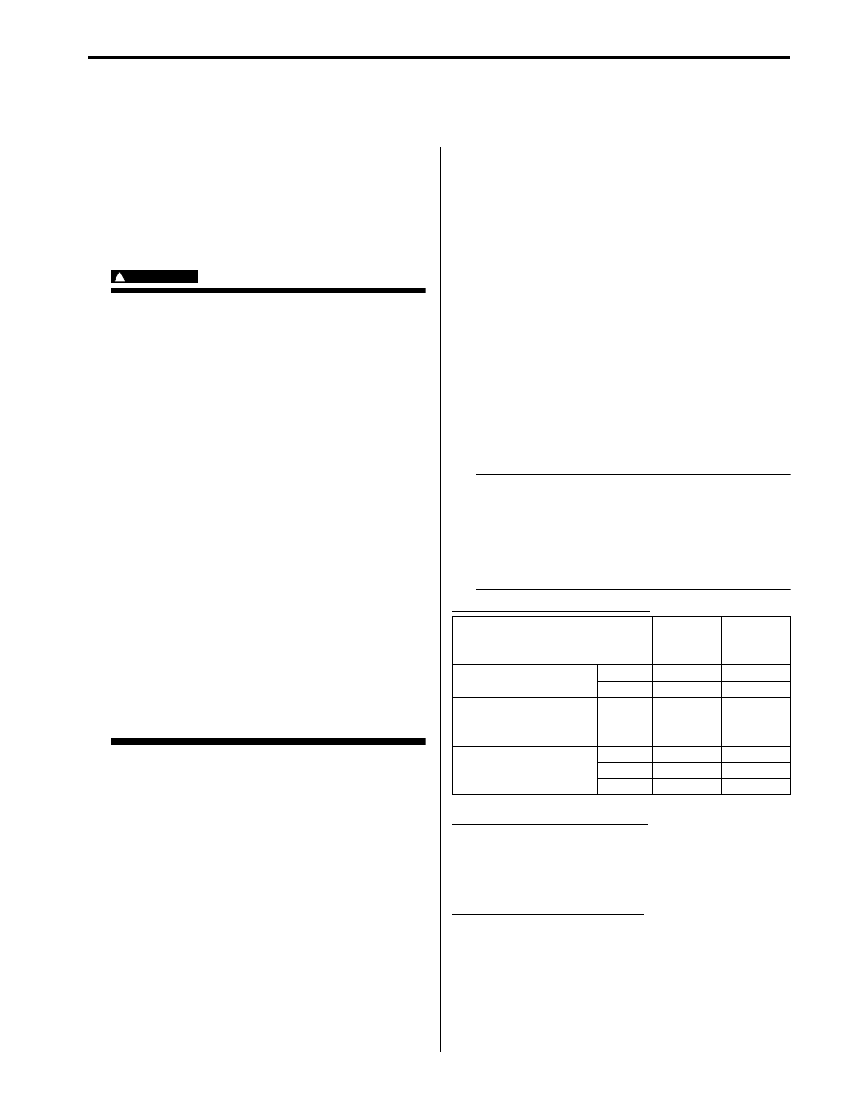
Coolant Circulation
S5JB0A1602001
While the engine is warmed up (thermostat closed), coolant circulates as follows.
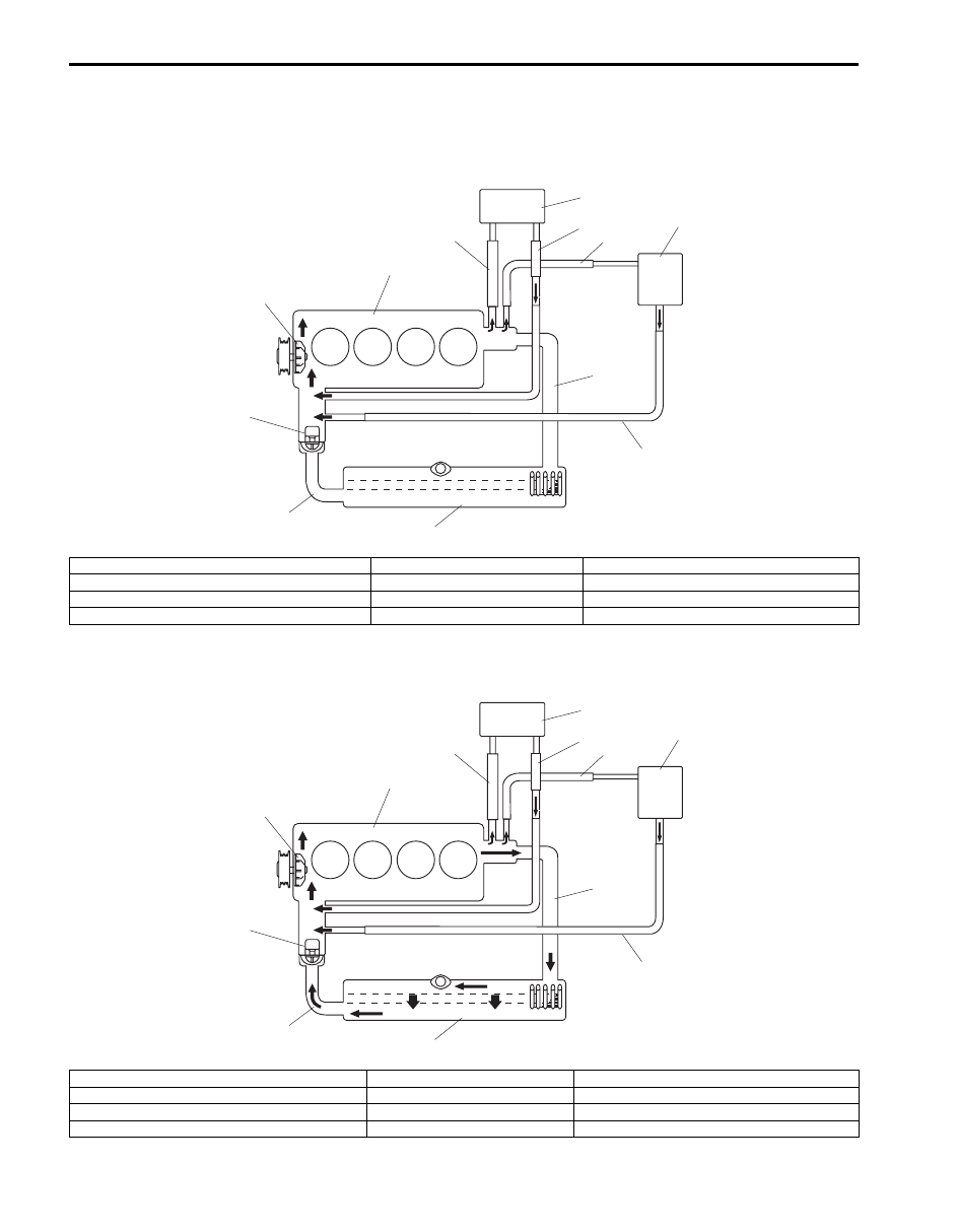
When coolant is warmed up to normal temperature and the thermostat opens, coolant passes through the radiator
core to be cooled as follows.
11
10
3
7
4
9
8
6
5
2
12
1
I5JB0A161001-01
1. Radiator inlet hose
5. Thermostat
9. Heater core inlet hose
2. Radiator outlet hose
6. Water pump
10. Heater core outlet hose
3. Throttle body inlet hose
7. Throttle body
11. Heater core
4. Throttle body outlet hose
8. Engine
12. Radiator
11
10
3
7
4
9
8
6
5
2
12
1
I5JB0A161002-01
1. Radiator inlet hose
5. Thermostat
9. Heater core inlet hose
2. Radiator outlet hose
6. Water pump
10. Heater core outlet hose
3. Throttle body inlet hose
7. Throttle body
11. Heater core
4. Throttle body outlet hose
8. Engine
12. Radiator

Engine Cooling System: 1F-3
Diagnostic Information and Procedures
Engine Cooling Symptom Diagnosis
S5JB0A1604001
Condition
Possible cause
Correction / Reference Item
Engine overheats
(Radiator fan operates)
Loose or broken water pump belt
Adjust or replace.
Not enough coolant
Check coolant level and add as necessary.
Faulty thermostat
Replace.
Faulty water pump
Replace.
Dirty or bent radiator fins
Clean or remedy.
Coolant leakage on cooling system
Repair.
Clogged radiator
Check and replace radiator as necessary.
Faulty radiator cap
Replace.
Improper ignition timing
Adjust.
Dragging brakes
Adjust brake.
Slipping clutch
Adjust or replace.
Poor charge battery
Check and replace as necessary.
Poor generation generator
Check and repair.
ECT sensor faulty
Check and replace as necessary.
Radiator cooling fan relay No.2 and/or
No.3 faulty
Check and replace as necessary.
Radiator fan motor faulty
Check and replace as necessary.
ECM faulty
Check and replace as necessary.
Wiring or grounding faulty
Repair as necessary.
Equipped with too much electric load
part(s)
Dismount.
Engine overheats
(Radiator fan does not
operate)
Fuse blown
Check 15 A fuse of relay/fuse box and check
for short circuit to ground.
Radiator cooling fan relay No.1 faulty
Check and replace as necessary.
ECT sensor faulty
Check and replace as necessary.
Radiator cooling fan motor faulty
Check and replace as necessary.
Wiring or grounding faulty
Repair as necessary.
ECM faulty
Check and replace as necessary.
Нет комментариевНе стесняйтесь поделиться с нами вашим ценным мнением.
Текст