Suzuki Grand Vitara JB416 / JB420. Manual — part 120

1E-16 Engine Lubrication System: For J20 Engine
4) Install new gasket and drain plug (2) to oil pan after
applying engine oil.
Tighten drain plug to specified torque.
Tightening torque
Oil drain plug (c): 35 N·m (3.5 kgf-m, 25.5 lb-ft)
5) Install front suspension frame referring to “Front
Suspension Frame, Stabilizer Bar and/or Bushings
Removal and Installation in Section 2B”.
6) Install engine under cover.
7) Install oil level gauge.
8) Refill engine with engine oil referring to “Engine Oil
and Filter Change in Section 0B”.
Oil Pan and Oil Pump Strainer Cleaning
S5JB0A1526003
• Clean mating surface of oil pan and cylinder block.
Remove oil, old sealant and dust from mating
surfaces and oil pan inside.
• Clean oil pump strainer screen.
Oil Pump Components
S5JB0A1526004
(a)
1
2, (c)
(b)
I5JB0A152009-01
I5JB0A152010-02
1. Cylinder block
6. Oil pump mounting bolt (M8 bolt)
11. Oil pump chain guide nut
: 25 N
⋅m (2.5 kgf-m, 18.0 lb-ft)
2. Oil pump relief valve set
: Replace as a set.
7. Oil pump case bolt
12. Oil pump case No.1
: 12 N
⋅m (1.2 kgf-m, 9.0 lb-ft)
3. Baffle plate
8. Oil pump relief valve retainer
13. Oil pump case No.2
: 28 N
⋅m (2.5 kgf-m, 20.5 lb-ft)
4. Pin No.1
9. Oil pump chain guide
14. Pin No.3
: 11 N
⋅m (1.1 kgf-m, 8.0 lb-ft)
5. Pin No.2
10. Oil pump chain guide plate
15. Baffle plate bolt (M6 bolt)
: 11 N
⋅m (1.1 kgf-m, 8.0 lb-ft)
Engine Lubrication System: For J20 Engine 1E-17
Oil Pump Removal and Installation
S5JB0A1526005
CAUTION
!
Don’t remove sprocket and inner rotor from
oil pump, otherwise damage of oil pump
center shaft and abnormal operation of oil
pump could result.
Removal
1) Disconnect negative cable at battery.
2) Drain engine oil referring to “Engine Oil and Filter
3) Remove oil pan and oil pump strainer.
Refer to “Oil Pan and Oil Pump Strainer Removal
and Installation: For J20 Engine”.
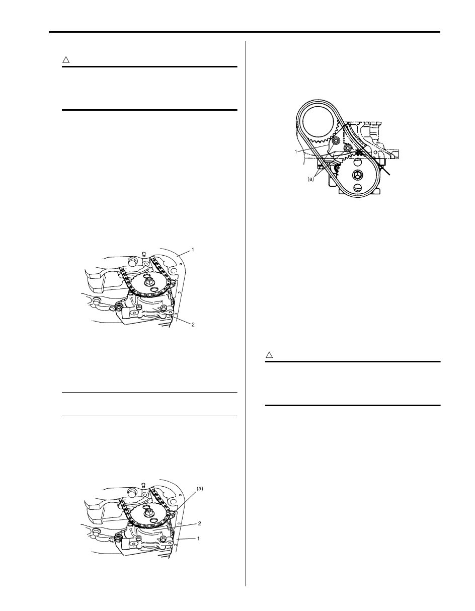
4) Remove baffle plate from lower crank case (1).
5) Remove oil pump chain guide.
6) Remove oil pump (2) with sprocket from lower crank
case (1).
Installation
1) Install oil pump (2) and baffle plate to lower crank
case (1) and tighten bolts to specified torque.
NOTE
When installing oil pump, be careful not to
allow pins to fall off.
Tightening torque
Oil pump mounting bolt (M8 bolt) (a): 25 N·m (
2.5 kgf-m, 18.0 lb-ft)
Baffle plate bolt (M6 bolt): 11 N·m (1.1 kgf-m, 8.0
lb-ft)
2) Install oil pump chain guide (1), and tighten bolts to
specified torque.
Tightening torque
Oil pump chain guide nut (a): 11 N·m (1.1 kgf-m,
8.0 lb-ft)
3) Install oil pan and oil pump strainer.
Refer to “Oil Pan and Oil Pump Strainer Removal
and Installation: For J20 Engine”
4) Install front suspension frame referring to “Front
Suspension Frame, Stabilizer Bar and/or Bushings
Removal and Installation in Section 2B”.
5) Refill engine with engine oil referring to “Engine Oil
and Filter Change in Section 0B”.
6) Connect negative cable at battery.
7) After completing installation, check oil pressure by
running engine. Refer to “Oil Pressure Check: For
J20 Engine”.
Oil Pump Disassembly and Assembly
S5JB0A1526006
CAUTION
!
Don’t remove sprocket and inner rotor from
oil pump, otherwise damage of oil pump
center shaft and abnormal operation of oil
pump could result.
Disassembly
• Disassemble oil pump referring to “Oil Pump
Assembly
1) Wash, clean and then dry all disassembled parts.
2) Apply thin coat of engine oil to inner and outer rotors,
and inside surfaces of oil pump case.
3) Install outer rotor to pump case No.1.
4) Install relief valve (3), relief spring (2) and retainer (1)
to oil pump case No.2 (4).
Tighten retainer to specified torque.
Tightening torque
Oil pump relief valve retainer (a): 28 N·m (2.8
kgf-m, 20.5 lb-ft)
I2RH01150016-01
I2RH01150017-01
I5JB0A152011-01

1E-18 Engine Lubrication System: For J20 Engine
5) Install oil pump case pins (5) to oil pump case No.2.
6) Assemble oil pump. After assembling oil pump,
check to be sure that rotor turns smoothly by hand.
Tightening torque
Oil pump case bolt (a): 12 N·m (1.2 kgf-m, 9.0 lb-
ft)
Oil Pump Inspection
S5JB0A1526007
• Check outer rotor (3), inner rotor and oil pump cases
(1), (2) for excessive wear or damage.
If abnormal condition is found in above checks,
replace oil pump assembly.
• Check relief valve (4) for excessive wear or damage.
If abnormal condition is found in above checks,
replace oil pump relief valve set.
• Measure free length and tension of oil relief spring.
If the measured values of length or tension is less
than the specification, replace oil pump relief valve
set.
Oil relief spring
• Measure clearance of oil pump rotor and oil pump
case.
Radial Clearance
Check radial clearance between outer rotor (2) and case
No.1 (1), using thickness gauge (4).
If clearance exceeds its limit, replace oil pump assembly.
Limit on radial clearance between outer rotor and
case
0.20 mm (0.0079 in.)
5. Relief spring
6. Retainer
I2RH01150020-01
I2RH01150021-01
I2RH01150022-01
Item
Standard
Spring free
length
63.5 mm (2.5 in.)
Spring
preload
85.0 N for 52.0 mm (8.5 kg for 52.0
mm, 19.0 lb/2.05 in.)
3. Inner rotor
I2RH01150023-01
I2RH01150024-01
Engine Lubrication System: For J20 Engine 1E-19
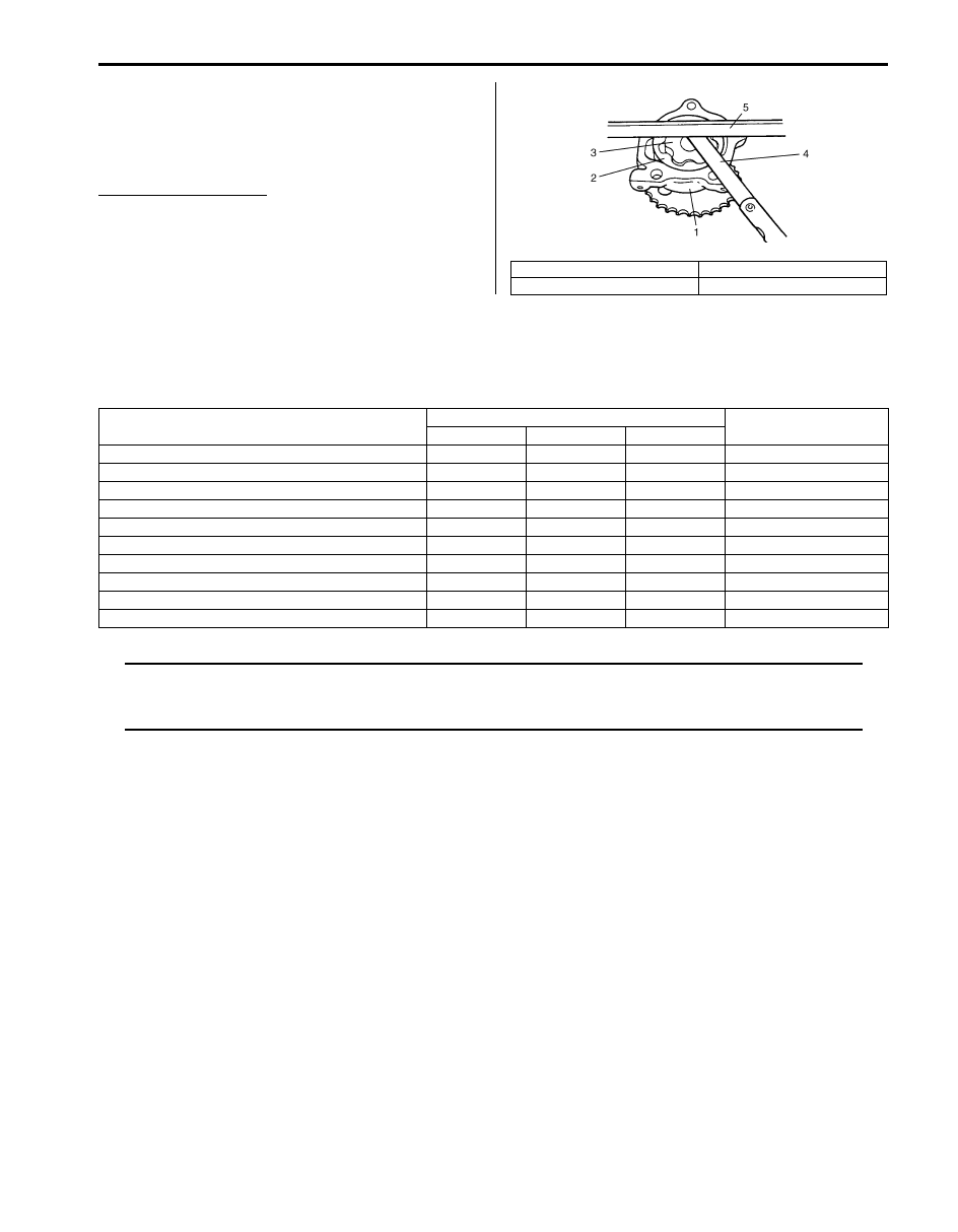
Side Clearance
Using straightedge (5) and thickness gauge (4),
measure side clearance.
If side clearance exceeds its limit, replace oil pump
assembly.
Limit on side clearance
0.11 mm (0.0043 in.)
Specifications
Tightening Torque Specifications
S5JB0A1527001
NOTE
The specified tightening torque is also described in the following.
“Oil Pan and Oil Pump Strainer Components: For J20 Engine”
“Oil Pump Components: For J20 Engine”
Reference:
For the tightening torque of fastener not specified in this section, refer to “Fastener Information in Section 0A”.
1. Oil pump case No.1
3. Inner rotor
2. Outer rotor
I2RH01150025-01
Fastening part
Tightening torque
Note
N
⋅m
kgf-m
lb-ft
Oil pressure switch
13
1.3
9.5
Oil pump strainer bolt
11
1.1
8.0
Oil pan bolt and nut
11
1.1
8.0
Transmission case No.1 bolt
85
8.5
61.5
Oil drain plug
35
3.5
25.5
Oil pump mounting bolt (M8 bolt)
25
2.5
18.0
Baffle plate bolt (M6 bolt)
11
1.1
8.0
Oil pump chain guide nut
11
1.1
8.0
Oil pump relief valve retainer
28
2.8
20.5
Oil pump case bolt
12
1.2
9.0
Нет комментариевНе стесняйтесь поделиться с нами вашим ценным мнением.
Текст