Suzuki Grand Vitara JB416 / JB420. Manual — part 410
10B-6 Body Electrical Control System:
Diagnostic Information and Procedures
BCM Self-Diagnosis Function
S5JB0AA204001
• BCM monitors conditions of the system components and its circuit with ignition switch turned to ON position. When
an abnormality in the system occurs, the area where that abnormality lies is stored in the memory of EEPROM in
BCM.
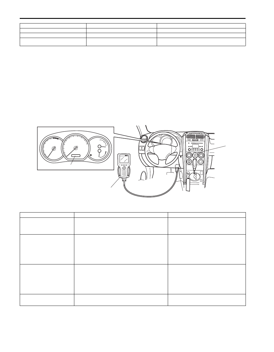
• DTC can be checked in either one of following ways.
– DTC can be checked by SUZUKI scan tool (2) connected to DLC (1).
– DTC can be read from flashing pattern of theft deterrent light (3). In addition, when theft deterrent light is flashing
for DTC outputting DTC is displayed on combinations meter (4) at the same time.
BCM input / output table
7. Door switch
17. Hazard warning switch
27. Front fog light switch
8. Interior light
18. Rear wiper switch
28. Turn signal and hazard warning relay
9. Luggage room light
19. Lighting switch
29. Key reminder switch (included in ignition switch)
10. Rear end door lock actuator
(incorporated in door switch)
20. Manual door lock switch
3
1
2
4
I5JB0AA20004-01
Control
Input
Output
Power door lock system
• Key cylinder switch
• Manual door lock switch
• Driver side door lock actuator
• Other than driver side door lock
actuator
Keyless entry system
• Key reminder switch
• Keyless entry receiver
• Driver side door switch
• Driver side door lock actuator
• Other than driver side door lock
actuator
• Turn signal and hazard warning relay
• Interior light
Keyless start system
(Door lock function)
• Keyless start control module
• Driver side door lock actuator
• Other than driver side door lock
actuator
• Turn signal and hazard warning relay
• Interior light
Rear wiper
• Rear wiper INT switch
• Rear wiper LO switch
• Rear wiper relay

Body Electrical Control System: 10B-7
Combination meter
• Lighting switch
• Brake fluid level switch
• Seat belt reminder lamp signal
• Generator
• Oil presser switch
• Parking brake switch
• Power/Normal mode select switch (for A/T
model only)
• Dimmer switch (high beam)
• Illumination controller (for auto-on headlight
model only)
• Door switch
• BCM DTC signal
• Combination meter
Interior light
• Each door switch
• Key reminder switch
• Interior light
• Luggage room light
Warning buzzer
• Key reminder switch
• Tail light switch
• Driver side door switch
• ECM (vehicle speed signal)
• TCM (reverse signal) (if equipped)
• 4WD control module (for 4WD model only)
• Keyless start control module (if equipped)
• Warning buzzer (located in BCM)
DRL system
• Lighting switch
• ECM (engine ON, OFF signal)
• Generator
• DRL indicator lamp control signal
• Headlight low relay
Auto-on headlight system
• Lighting switch
• Parking brake switch
• Auto-on headlight sensor
• Tail light relay
• Headlight low relay
Front fog light
• Lighting switch
• Front fog light switch
• Front fog light relay
Rear end door window
defogger and door mirror
heater
• Rear end door window defogger switch
(included in HVAC control module)
• Generator
• ECM (engine ON, OFF signal)
• Rear end door defogger window
relay
• Mirror heater relay (if equipped)
Illumination control (if
equipped)
• Lighting switch
• Illumination controller
• Illumination control of combination
meter and information display
(illumination cancel signal)
Door lock canceller
• SDM (air bag deployment signal)
• Driver side door lock actuator
• Other than driver side door lock
actuator
Theft deterrent light
• Key reminder switch
• Theft deterrent light (located in HVAC
control module)
Control
Input
Output
10B-8 Body Electrical Control System:
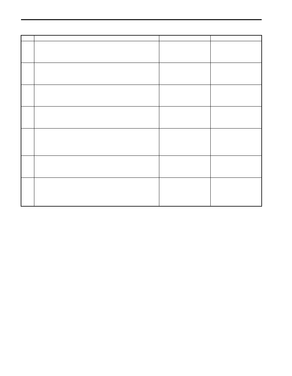
Body Electrical Control System Check
S5JB0AA204002
Step
Action
Yes
No
1
Customer complaint analysis
1) Perform customer complaint analysis.
Was customer complaint analysis performed?
Go to Step 2.
Perform customer
complaint analysis.
2
Problem symptom confirmation
1) Perform problem symptom confirmation.
Does trouble recur?
Go to Step 3.
Go to Step 7.
3
DTC check
1) Check DTC.
Is it malfunction code?
Go to Step 4.
Go to Step 5.
4
Troubleshooting for DTC
1) Check and repair according to DTC diag. flow.
Are check and repair completed?
Go to Step 7.
Check and repair
malfunction part(s).
5
Body electrical control system symptom diagnosis
1) Perform check and repair referring to “Symptom
Diagnosis” of system having a trouble.
Is there faulty condition?
Repair or replace
malfunction part(s).
Go to Step 6.
6
Check for intermittent problem
1) Check for intermittent problem.
Is there faulty condition?
Repair or replace
malfunction part(s).
Go to Step 7.
7
Final confirmation test
1) Clear DTC referring to “DTC Clearance”.
2) Check DTC referring to “DTC Check”.
Is there any DTC?
Go to Step 4.
End.

Body Electrical Control System: 10B-9
Customer Complaint Analysis
Record details of the problem (failure, complaint) and how it occurred as described by the customer.
For this purpose, use of such a questionnaire form as shown in the figure will facilitate collecting information to the
point required for proper analysis and diagnosis.
Customer questionnaire (example)
Problem Symptom Confirmation
Check if what the customer claimed in “Customer Questionnaire” is accurately found in the vehicle. If that symptom is
found, check whether the symptom is identified as a failure. (This step should be shared with the customer if possible.)
DTC check
Check DTC stored in BCM memory referring to “DTC Check”, record it and then clear it referring to “DTC Clearance”.
DTC indicates malfunction that occurred in the system but does not indicate whether it exists now or it occurred in the
past and the normal condition has been restored now. To check which case applies, clear DTC once and check
whether or not any fault exists.
Troubleshooting for DTC
Based on the DTC indicated in Step 3 and referring to applicable DTC flow, locate the cause of the trouble, namely in
a sensor, wire harness, connector, BCM or other part and repair or replace faulty parts.
Body Electrical Control System Symptom Diagnosis
Check the parts or system suspected as a possible cause referring to symptom diagnosis of each system.
Check for Intermittent Problem
Check parts where an intermittent trouble is easy to occur (e.g., wire harness, connector, etc.), referring to
“Intermittent and Poor Connection Inspection in Section 00”.
Final Confirmation Test
Confirm that the problem symptom has gone and the body electrical control system is free from any abnormal
conditions. If what has been repaired is related to the malfunction DTC, check DTC again and confirm that no DTC is
indicated.
I4RS0AA20013-01
Нет комментариевНе стесняйтесь поделиться с нами вашим ценным мнением.
Текст