Suzuki Grand Vitara JB416 / JB420. Manual — part 33

1A-81 Engine General Information and Diagnosis:
DTC Troubleshooting
NOTE
Before this trouble shooting is performed, read the precautions for DTC troubleshooting referring to
“Precautions For DTC Troubleshooting”.
DTC P0107: Manifold Absolute Pressure Circuit Low Input
S5JB0A1104021
Wiring Diagram
Refer to “DTC P0106: Manifold Absolute Pressure Range / Performance”.
DTC Detecting Condition and Trouble Area
NOTE
When DTC P0532 and P1501 are indicated together, it is possible that “GRY/RED” wire circuit open.
DTC Confirmation Procedure
1) Connect scan tool to DLC with ignition switch turned OFF.
2) Turn ON ignition switch and clear DTC using scan tool and warm up engine completely.
3) Run engine at idle speed for 1 min.
4) Check DTC and pending DTC.
Step
Action
Yes
No
1
Was “Engine and Emission Control System Check”
performed?
Go to Step 2.
Go to “Engine and
Emission Control
System Check”.
2
MAP sensor and its circuit check
1) Connect scan tool to DLC with ignition switch turned
OFF.
2) Turn ON ignition switch.
3) Check DTC.
Is there DTC P0107 or DTC P0108?
Go to applicable DTC
diag. flow.
Go to Step 3.
3
MAP sensor output signal check
1) Check MAP sensor according to “Manifold Absolute
Pressure (MAP) Sensor Inspection in Section 1C”.
Is it in good condition?
Go to Step 4.
Faulty MAP sensor.
4
MAP sensor circuit check
1) Check MAP sensor circuit referring to Step 3 to 6 of
“DTC P0107: Manifold Absolute Pressure Circuit Low
Input” or Step 3 to 8 of “DTC P0108: Manifold Absolute
Pressure Circuit High Input”.
Is circuit in good condition?
Go to Step 5.
Repair or replace.
5
Air intake system check
1) Check air intake system for clog or leak.
Is it in good condition?
Substitute a known-
good ECM and recheck.
Repair or replace.
DTC detecting condition
Trouble area
Manifold absolute pressure sensor output voltage is lower
than specified value for specified time continuously.
(1 driving cycle detection logic)
• Manifold absolute pressure sensor circuit
• Manifold absolute pressure sensor
• ECM
Engine General Information and Diagnosis: 1A-82
DTC Troubleshooting
NOTE
Before this trouble shooting is performed, read the precautions for DTC troubleshooting referring to
“Precautions For DTC Troubleshooting”.
Step
Action
Yes
No
1
Was “Engine and Emission Control System Check”
performed?
Go to Step 2.
Go to “Engine and
Emission Control
System Check”.
2
MAP sensor and its circuit check
1) Connect scan tool to DLC with ignition switch turned
OFF.
2) Turn ON ignition switch.
3) Check intake manifold pressure displayed on scan tool.
Is it 0 kPa (0 in.Hg)?
Go to Step 3.
Intermittent trouble.
Check for intermittent
referring to “Intermittent
and Poor Connection
Inspection in Section
00”.
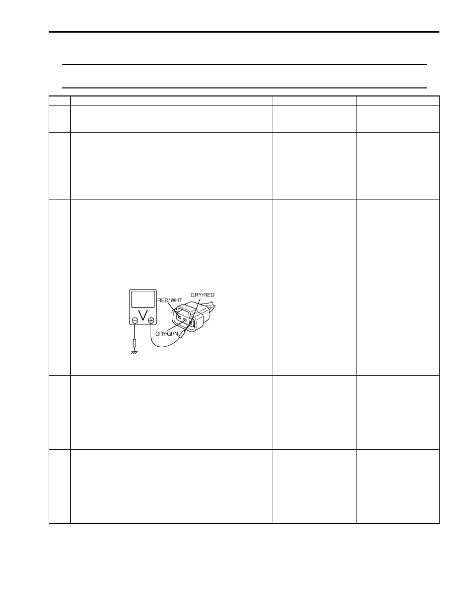
3
MAP sensor power supply voltage check
1) Disconnect connector from MAP sensor with ignition
switch turned OFF.
2) Check for proper connection of MAP sensor at “GRY/
RED”, “RED/WHT” and “GRY/GRN” wire terminals.
3) Turn ON ignition switch, measure voltage between
engine ground and “GRY/RED” wire terminal of MAP
sensor connector.
Is voltage 4 – 6 V?
Go to Step 5.
Go to Step 4.
4
MAP sensor power supply circuit check
1) Disconnect connectors from ECM with ignition switch
turned OFF.
2) Measure resistance between “GRY/RED” wire terminal
of MAP sensor connector and “C37-14” terminal of ECM
connector.
Is resistance below 3
Ω
?
Go to Step 5.
“GRY/RED” wire is open
circuit.
5
MAP sensor signal circuit check
1) Connect connectors to ECM with ignition switch turned
OFF.
2) Measure voltage between “RED/WHT” wire terminal of
MAP sensor connector and engine ground with ignition
switch turned ON.
Is voltage 4 – 6 V?
Go to Step 7.
Go to Step 6.
I5JB0A110035-01

1A-83 Engine General Information and Diagnosis:
DTC P0108: Manifold Absolute Pressure Circuit High Input
S5JB0A1104022
Wiring Diagram
Refer to “DTC P0106: Manifold Absolute Pressure Range / Performance”.
DTC Detecting Condition and Trouble Area
NOTE
When DTC P0113, P0118 and P0533 are indicated together, it is possible that “GRY/GRN” wire circuit is
open.
DTC Confirmation Procedure
1) Connect scan tool to DLC with ignition switch turned OFF.
2) Turn ON ignition switch and clear DTC using scan tool and warm up engine completely.
3) Run engine at idle speed for 1 min.
4) Check DTC and pending DTC.
DTC Troubleshooting
NOTE
Before this trouble shooting is performed, read the precautions for DTC troubleshooting referring to
“Precautions For DTC Troubleshooting”.
6
MAP sensor signal circuit check
1) Disconnect connectors from ECM with ignition switch
turned OFF.
2) Measure resistance between “C37-55” terminal of ECM
connector and vehicle body ground.
Is resistance infinity?
Go to Step 7.
“RED/WHT” wire is
shorted to ground
circuit.
7
MAP sensor output signal check
1) Check MAP sensor according to “Manifold Absolute
Pressure (MAP) Sensor Inspection in Section 1C”.
Is it in good condition?
Substitute a known-
good ECM and recheck.
Faulty MAP sensor.
Step
Action
Yes
No
DTC detecting condition
Trouble area
Manifold absolute pressure sensor output voltage is higher
than specified value for specified time continuously.
(1 driving cycle detection logic)
• Manifold absolute pressure sensor circuit
• Manifold absolute pressure sensor
• ECM
Step
Action
Yes
No
1
Was “Engine and Emission Control System Check”
performed?
Go to Step 2.
Go to “Engine and
Emission Control
System Check”.
2
MAP sensor and its circuit check
1) Connect scan tool to DLC with ignition switch OFF.
2) Turn ignition switch ON.
3) Check intake manifold pressure displayed on scan tool.
Is it 127 kPa (37.5 in.Hg)?
Go to Step 3.
Intermittent trouble.
Check for intermittent
referring to “Intermittent
and Poor Connection
Inspection in Section
00”.
Engine General Information and Diagnosis: 1A-84
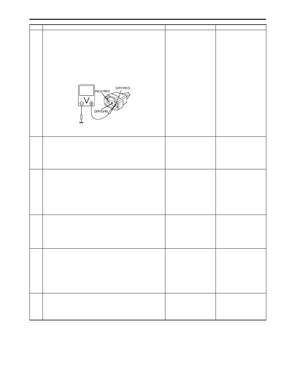
3
MAP sensor power supply voltage check
1) Disconnect connector from MAP sensor with ignition
switch turned OFF.
2) Check for proper connection of MAP sensor at “GRY/
RED”, “RED/WHT” and “GRY/GRN” wire terminals.
3) Turn ON ignition switch, measure voltage between
engine ground and “GRY/RED” wire terminal of MAP
sensor connector.
Is voltage 4 – 6 V?
Go to Step 4.
“GRY/RED” wire
shorted to power circuit.
4
MAP sensor ground circuit check
1) Measure resistance between “GRY/GRN” wire terminal
of MAP sensor connector and engine ground with
ignition switch turned OFF.
Is resistance below 3
Ω
?
Go to Step 6.
Go to Step 5.
5
Ground circuit check
1) Measure resistance between “C37-57” terminal of ECM
connector and vehicle body ground.
Is resistance below 3
Ω
?
“GRY/GRN” wire is
open or high resistance
circuit.
ECM grounds “C37-58”,
“C37-48”, “C37-30”,
“C37-29” and/or “C37-
15” circuit are open or
high resistance.
If wires are OK,
substitute a known-
good ECM and recheck.
6
MAP sensor signal circuit check
1) Turn ON ignition switch.
2) Measure voltage between “RED/WHT” wire terminal of
MAP sensor connector and engine ground.
Is voltage 4 – 6 V?
Go to Step 8.
Go to Step 7.
7
MAP sensor signal circuit check
1) Disconnect connectors from ECM with ignition switch
turned OFF.
2) Measure resistance between “RED/WHT” wire terminal
of MAP sensor connector and “C37-55” terminal of ECM
connector.
Is resistance below 2
Ω
?
“RED/WHT” wire is
shorted to power supply
circuit.
“RED/WHT” wire is
open or high resistance
circuit.
8
MAP sensor output signal check
1) Check MAP sensor according to “Manifold Absolute
Pressure (MAP) Sensor Inspection in Section 1C”.
Is it in good condition?
Substitute a known-
good ECM and recheck.
Faulty MAP sensor.
Step
Action
Yes
No
I5JB0A110035-01
Нет комментариевНе стесняйтесь поделиться с нами вашим ценным мнением.
Текст