Suzuki Grand Vitara JB416 / JB420. Manual — part 39
1A-105 Engine General Information and Diagnosis:
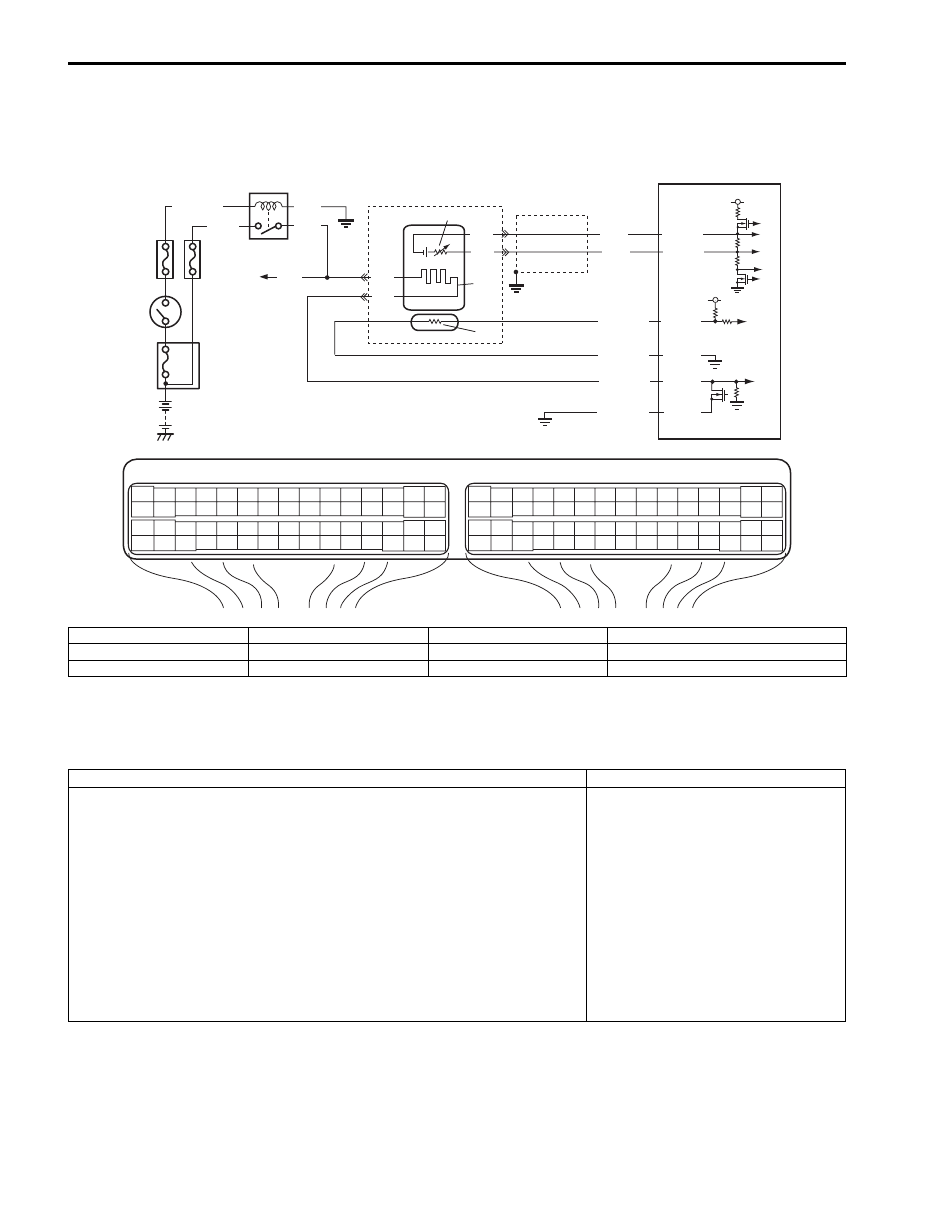
DTC P0131 / P0132 / P0134: O2 Sensor (HO2S) Circuit Low Voltage / High Voltage / No Activity
Detected (Sensor-1)
S5JB0A1104032
Wiring Diagram
A/F Sensor Description
Refer to “A/F Sensor Description”.
DTC Detecting Condition and Trouble Area
E23
C37
3
4
18
19
5
6
7
10
11
17
20
47
46
49
50
51
21
22
52
16
25
9
24
14
29
55
57
54 53
59
60
58
2
26
27
28
15
30
56
48
32
31
34
35
36
37
40
42
39 38
44
45
43
41
33
1
12
13
23
8
3
4
18
19
5
6
7
10
11
17
20
47
46
49
50
51
21
22
52
16
25
9
24
14
29
55
57
54 53
59
60
58
2
26
27
28
15
30
56
48
32
31
34
35
36
37
40
42
39 38
44
45
43
41
33
1
12
13
23
8
4
3
9
PNK
6
2
1
8
5
BLK/WHT
BLK
PNK
*GRN
C37-34
C37-32
C37-37
C37-38
BLK
BLK
BLU
WHT
C37-35
C37-31
WHT
BLK
RED/YEL
RED/BLU
PNK/BLU
BLK/YEL
10
7
11
5 V
5 V
I5JB0A110044-02
1. HO2 heater relay
4. “O2 HTR” fuse
7. Heater
10. Adjusting resistor
2. Shield wire
5. “IG COIL” fuse
8. To HO2S-2 heater
11. Sensor
3. Ignition switch
6. A/F sensor
9. ECM
*: For M16 engine
DTC detecting condition
Trouble area
DTC P0131:
A/F sensor (LF+) terminal voltage is lower than specified range or A/F sensor
output current is lower than specification.
(2 driving cycle detection logic)
DTC P0132:
A/F sensor (LF+) terminal voltage is higher than specified range or A/F sensor
output current is more than specification.
(2 driving cycle detection logic)
DTC P0134:
Impedance of A/F sensor element is higher than specification for more than
160 sec even though A/F sensor heater is turned ON for more than specified
time with engine running. (A/F sensor or sensor circuit open)
(2 driving cycle detection logic)
• A/F sensor circuit
• A/F sensor
• ECM

Engine General Information and Diagnosis: 1A-106
DTC Confirmation Procedure
1) With ignition switch turned OFF, connect scan tool.
2) Turn ON ignition switch and clear DTC using scan tool.
3) Start engine and warm up to normal operating temperature.
4) Run engine at idle speed for 1 min. or more.
5) Check DTC and pending DTC.
DTC Troubleshooting
NOTE
Before this trouble shooting is performed, read the precautions for DTC troubleshooting referring to
“Precautions For DTC Troubleshooting”.
DTC P0133: O2 Sensor (HO2S) Circuit Slow Response (Sensor-1)
S5JB0A1104033
Wiring Diagram
Refer to “DTC P0131 / P0132 / P0134: O2 Sensor (HO2S) Circuit Low Voltage / High Voltage / No Activity Detected
(Sensor-1)”.
Step
Action
Yes
No
1
Was “Engine and Emission Control System Check”
performed?
Go to Step 2.
Go to “Engine and
Emission Control
System Check”.
2
Is there DTC(s) other than A/F sensor?
Go to applicable DTC
diag. flow.
Go to Step 3.
3
A/F sensor signal check
1) Connect scan tool to DLC with ignition switch turned
OFF.
2) Warm up engine to normal operating temperature and
keep it at 2000 r/min. for 60 sec.
3) Repeat racing engine (Repeat depressing accelerator
pedal 5 to 6 times continuously to enrich A/F mixture and
take foot off from pedal to enlean it).
Does A/F sensor output current between –0.2 mA and 0.2
mA?
Intermittent trouble.
Check for intermittent
referring to “Intermittent
and Poor Connection
Inspection in Section
00”.
Go to Step 4.
4
A/F sensor circuit check
1) Disconnect connector from A/F sensor and ECM with
ignition switch turned OFF.
2) Check for proper connection of each A/F sensor circuit
terminal to A/F sensor connector and to ECM connector.
3) If connections are OK, check A/F sensor circuit for the
following.
• Resistance of each sensing circuit wire of A/F sensor
between A/F sensor connector and ECM connector is
less than 2
Ω
• Resistance between sensing circuit wires of A/F
sensor connector are infinity
• Resistance between each sensing circuit wire of A/F
sensor connector and vehicle body ground is infinity
• Voltage of between each sensing circuit wire of A/F
sensor connector and vehicle body ground is 0 V with
ignition switch tuned ON
Is it in good condition?
Replace A/F sensor.
Repair or replace
defective wire.
1A-107 Engine General Information and Diagnosis:
A/F Sensor Description
Refer to “A/F Sensor Description”.
DTC Detecting Condition and Trouble Area
DTC Confirmation Procedure
WARNING
!
• When performing a road test, select a place where there is no traffic or possibility of a traffic
accident and be very careful during testing to avoid occurrence of an accident.
• Road test should be carried out by 2 persons, a driver and a tester, on a level road.
NOTE
Check to make sure that following conditions are satisfied when using this “DTC Confirmation
Procedure”.
• Intake air temperature at engine start: –10
°C (14 °F) to 80 °C (176 °F)
• Intake air temperature: –10
°C (14 °F) to 70 °C (158 °F)
• Engine coolant temperature: 70
°C (158 °F) to 150 °C (302 °F)
• Altitude (barometric pressure): 2400 m, 8000 ft or less (560 mmHg, 75 kPa or more)
1) With ignition switch turned OFF, connect scan tool.
2) Turn ON ignition switch and clear DTC using scan tool.
3) Start engine and warm up to normal operating temperature.
4) Drive vehicle at 40 mph (60 km/h) or higher. (engine speed: 2500 – 3000 r/min.)
5) Keep above vehicle speed for 6 min. or more. (Throttle valve opening is kept constant in this step.)
6) Release accelerator pedal and with engine brake applied, keep vehicle coasting (with fuel cut for 3 sec. or more)
and then stop vehicle.
7) Check if DTC and pending DTC exist by using scan tool. If not, check if oxygen sensor monitoring test has been
completed by using scan tool. If not in both of above checks (i.e., no DTC and pending DTC and oxygen sensor
monitoring test not completed), check vehicle condition (environmental) and repeat Step 3) through 6).
DTC Troubleshooting
NOTE
Before this trouble shooting is performed, read the precautions for DTC troubleshooting referring to
“Precautions For DTC Troubleshooting”.
DTC detecting condition
Trouble area
Ratio between integrated value of A/F sensor output variation and integrated value of
short term fuel trim variation is more than specification while vehicle is running
constant speed and low engine load after warmed up.
(*2 driving cycle detection logic, monitoring once / 1 driving)
• A/F sensor
• Air intake system
• Exhaust system
Step
Action
Yes
No
1
Was “Engine and Emission Control System Check”
performed?
Go to Step 2.
Go to “Engine and
Emission Control
System Check”.
2
DTC check
Is there DTC(s) other than P0133?
Go to applicable DTC
diagnosis flow.
Go to Step 3.
3
Intake system and exhaust system for leakage check
Are intake system and exhaust system in good condition?
Replace A/F sensor.
Repair or replace
defective leakage parts.
Engine General Information and Diagnosis: 1A-108
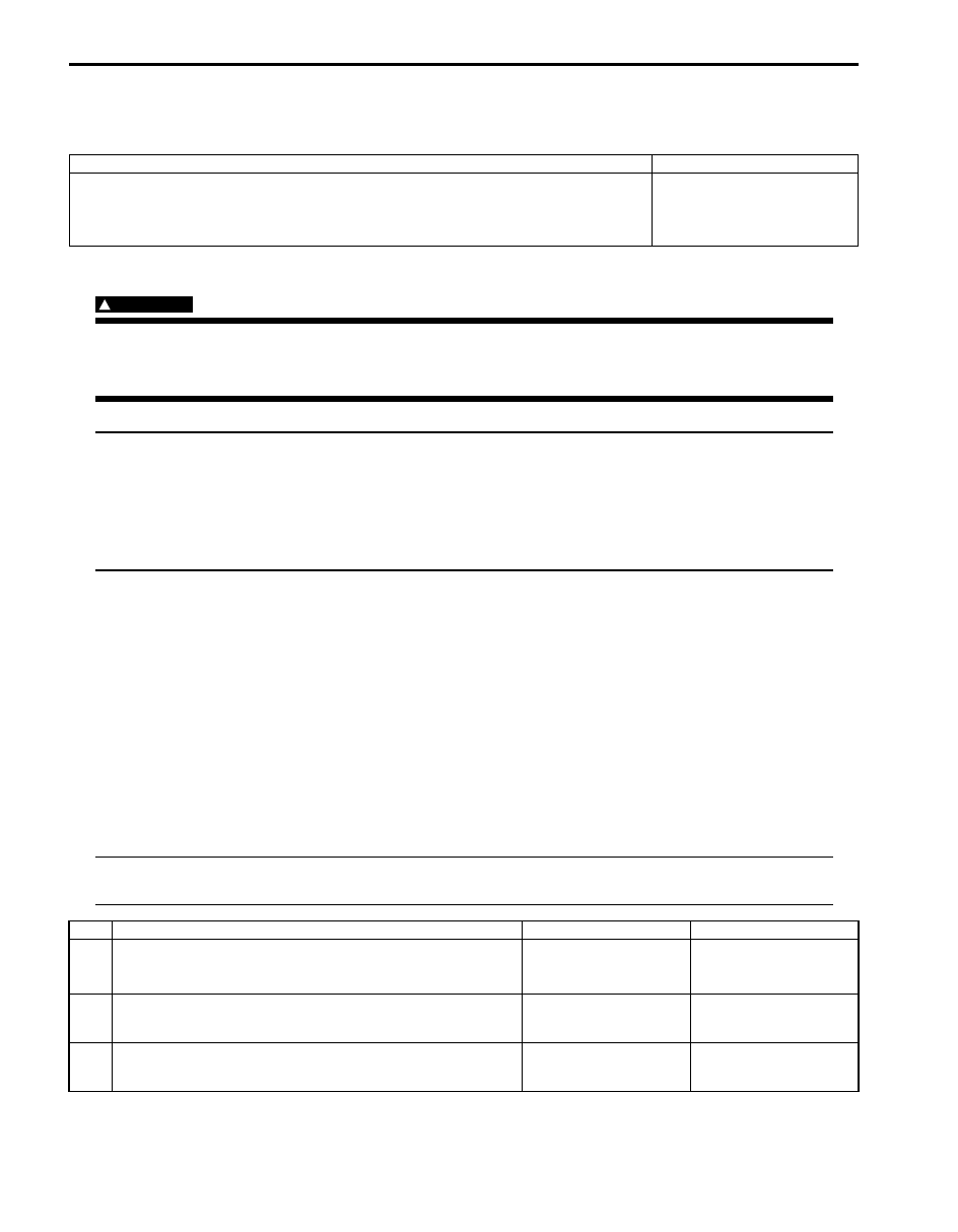
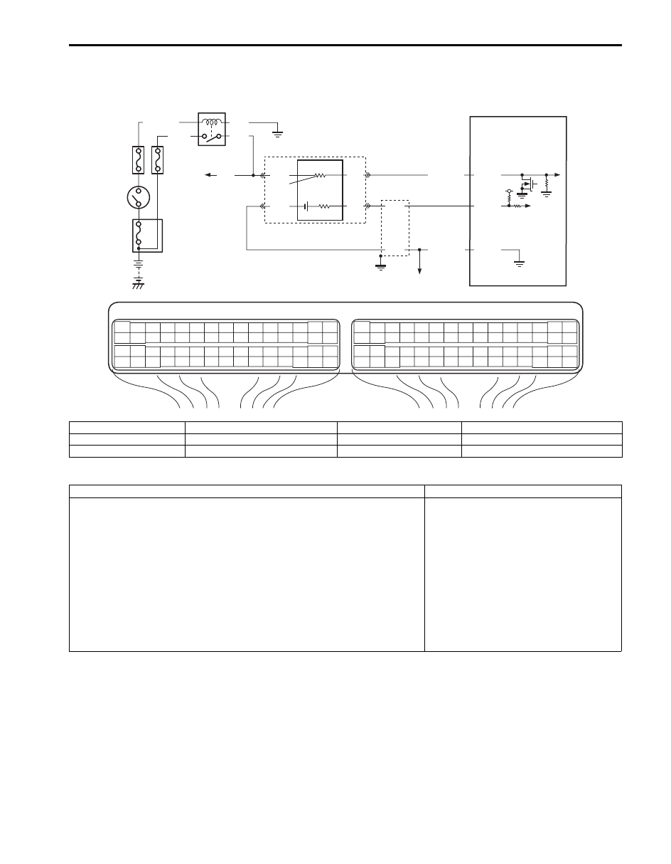
DTC P0137 / P0138: O2 Sensor (HO2S) Circuit Low Voltage / High Voltage (Sensor-2)
S5JB0A1104035
Wiring Diagram
DTC Detecting Condition and Trouble Area
E23
C37
3
4
18
19
5
6
7
10
11
17
20
47
46
49
50
51
21
22
52
16
25
9
24
14
29
55
57
54 53
59
60
58
2
26
27
28
15
30
56
48
32
31
34
35
36
37
40
42
39 38
44
45
43
41
33
1
12
13
23
8
3
4
18
19
5
6
7
10
11
17
20
47
46
49
50
51
21
22
52
16
25
9
24
14
29
55
57
54 53
59
60
58
2
26
27
28
15
30
56
48
32
31
34
35
36
37
40
42
39 38
44
45
43
41
33
1
12
13
23
8
4
3
9
RED
GRN
PNK
BLK
C37-47
C37-11
C37-57
6
2
7
10
BLK
BLU
WHT
BLK/RED
GRY/GRN
1
8
5
5V
BLK/WHT
BLK
PNK
*GRN
I5JB0A110045-01
1. HO2S heater relay
4. “O2 HTR” fuse
7. Heater
10. To other sensors
2. Shield wire
5. “IG COIL” fuse
8. To A/F sensor heater
*: For M16 engine
3. Ignition switch
6. HO2S-2
9. ECM
DTC detecting condition
Trouble area
DTC P0137:
HO2S-2 voltage is lower than 0.4 V for more than specified time
continuously while vehicle is driving with high engine load (high speed).
And HO2S-2 max. voltage minus HO2S-2 min. voltage is less than 0.2 V
for specified time continuously.
(2 driving cycle detection logic)
DTC P0138:
HO2S-2 voltage is higher than 0.85 V for more than specified time
continuously while vehicle is driving with high engine load (high speed).
And HO2S-2 max. voltage minus HO2S-2 min. voltage is less than 0.2 V
for specified time continuously.
(2 driving cycle detection logic)
• HO2S-2
• HO2S-2 circuit
• Fuel system
• ECM
• Fuel shortage
• Exhaust system
• Air intake system
Нет комментариевНе стесняйтесь поделиться с нами вашим ценным мнением.
Текст