Suzuki Grand Vitara JB416 / JB420. Manual — part 240

5A-94 Automatic Transmission/Transaxle:
7) Disconnect shift solenoid–A connector (1), shift
solenoid–B connector (2), TCC pressure control
solenoid connector (4) and Pressure control solenoid
connector (3).
8) Remove solenoid valves.
9) After removing bolt (1) pull out transmission wire
connector (2) from transmission case.
CAUTION
!
When pulling transmission wire harness out
of transmission case, take care not to
damage connectors and transmission fluid
temperature sensor at narrow exist of case.
Careless sensor treatment might cause
sensor malfunction.
Installation
Remove removal procedure to install transmission fluid
temperature sensor, noting the following points.
• For details of solenoid valves and their connectors
installation, refer to “Automatic Transmission Unit
Assembly”. Use new O-ring.
• For details of A/T oil pan installation, refer to
“Automatic Transmission Unit Assembly”.
• Fill A/T fluid and check fluid level according to
procedure described in “A/T Fluid Change”.
• Check for fluid leakage after warming up A/T.
• Tighten transmission wire connector bolt to specified
torque referring to “Automatic Transmission Unit
Assembly”.
Transmission Fluid Temperature Sensor
Inspection
S5JB0A5106063
Immerse transmission fluid temperature sensor (1) in
water or oil. Check transmission fluid temperature
sensor resistance between terminals of connector. Thus
make sure its resistance decreases as temperature
rises.
If sensor resistance is out of specification, replace
solenoid wire harness (2).
Transmission fluid temperature sensor resistance
10
°C (50 °F): 6.445 kΩ
25
°C (77 °F): 3.5 kΩ
110
°C (230 °F): 0.247 kΩ
3
4
1
2
I5JB0A510058-01
1
2
I5JB0A510059-01
4 3 2 1
8 7 6 5
2
1
I5JB0A510060-01
Automatic Transmission/Transaxle: 5A-95
Transmission Control Module (TCM) Removal
and Installation
S5JB0A5106064
CAUTION
!
TCM consists of highly precise parts, so
when handling it, be careful not to expose it
to excessive shock.
Removal
1) Disconnect negative cable at battery.
2) Disable air bag system.
Refer to “Disabling Air Bag System in Section 8B”.
3) Remove glove box.
4) Disconnect connectors from TCM (1).
5) Remove TCM with 4WD control module by removing
its nuts, and then separate TCM and 4WD control
module.
Installation
Reverse removal procedure noting the following points.
• Connect TCM connectors securely.
• Be sure to enable air bag system after TCM is back in
place. Refer to “Enabling Air Bag System in Section
8B”.
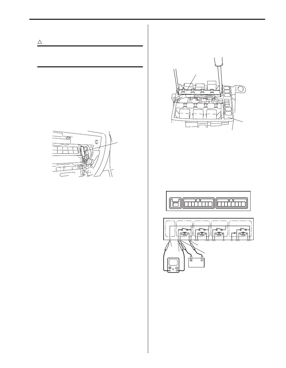
A/T Relay Inspection
S5JB0A5106092
1) Disconnect negative cable at battery.
2) Remove integration relay No.2 (1) from fuse box
No.2 (2).
3) Check that there is no continuity between terminals
“E41-1” and “E38-8”.
If there is continuity, replace relay.
4) Connect battery positive (+) terminal to terminal
“E38-6” of relay. Connect battery negative (–)
terminal to terminal “E38-7” of relay. Check for
continuity between terminal “E41-1” and “E38-8”. If
there is no continuity when relay is connected to the
battery, replace integration relay No.2.
1
I5JB0A510061-01
2
1
I5JB0A130031-02
1
1
2
3
4
5
6
7
8
1
2
3
4
5
6
7
8
E41
E41
E41
E37
E38
“E38-6”
“E41-1”
“E38-7”
“E38-8”
I5JB0A510159-01

5A-96 Automatic Transmission/Transaxle:
Automatic Transmission Unit Components
S5JB0A5106065
22
(b)
(b)
(c)
(c)
(c)
(c)
(d)
(e)
(e)
(e)
(f)
32
17
16
9
14
13
9
(c)
9
15
8
7
4
3
5
6
10
11
12
18
19
25
26
11
23
24
21
20
27
(f)
28
(f)
29
(a)
2
(a)
1
30
(b)
31
(b)
32
33
A
(a)
34
I5JB0A510003-02

Automatic Transmission/Transaxle: 5A-97
Automatic Transmission Assembly
Dismounting and Remounting
S5JB0A5106066
Dismounting
1) Dismount engine with transmission and transfer
referring to “Engine Assembly Removal and
Installation: For J20 Engine in Section 1D”.
2) Disconnect connectors from output shaft speed
sensor, input shaft speed sensor, transmission range
sensor, transmission wire, transfer actuator,
differential lock switch and 4L/N switch release their
wire harnesses from clamps.
3) Remove transfer from transmission.
4) Remove engine earth cable.
5) Remove engine rear mounting member and rear
mounting.
6) Remove oil filler tube.
7) Remove cooler hose.
8) Remove drive plate cover, and then remove drive
plate bolts by holding crankshaft pulley bolt
stationary.
9) Remove Starting Motor referring to “Starting Motor
Dismounting and Remounting in Section 1I”.
10) Remove transmission assembly from engine
assembly.
Installation
For remounting, reverse dismounting procedure noting
the following points.
• Tighten each bolts and nuts referring to “Automatic
• Tighten drive plate bolt No.1 (1) first and then tighten
drive plate bolts No.2 (2).
• Set each clamp for wiring securely.
• Fill A/T fluid referring to “A/T Fluid Change”.
• Connect battery and check function of engine and
transmission.
1. Torque converter mounting bolt No.1
: After tightening torque converter
mounting bolt No.1, tighten torque
converter mounting bolt No.2.
11. Transmission to engine bolt
21. Output shaft speed sensor
31. Engine earth cable bolt
2. Torque converter mounting bolt No.2
12. Exhaust pipe No.2 bracket bolt
22. Engine harness
32. Harness bracket bolt
3. Drive plate
13. Starting motor
23. Transfer
33. Harness bracket
4. Torque converter
14. Starting motor bolt
24. Transfer to transmission bolt
34. Drive plate bolt
5. Oil cooler hose
15. Transmission
25. Engine rear mounting
: 65 N
⋅m (6.5 kgf-m, 47.0
lb-ft)
6. Clamp
16. Oil filler tube bolt
26. Engine rear mounting bolt
: 10 N
⋅m (1.0 kgf-m, 7.5
lb-ft)
7. Drive plate cover bolt
17. Oil filler tube
27. Engine rear mounting bracket
: 80 N
⋅m (8.0 kgf-m, 58.0
lb-ft)
8. Drive plate cover
18. Input shaft speed sensor
28. Engine rear mounting bracket
bolt
: 50 N
⋅m (5.0 kgf-m, 36.5
lb-ft)
9. Engine to transmission bolt
19. Output shaft speed sensor
29. Mounting member bolt
: 23 N
⋅m (2.3 kgf-m, 17.0
lb-ft)
10. Exhaust pipe No.2 bracket
20. Transmission wire connector
30. Engine earth cable
: 55 N
⋅m (5.5 kgf-m, 40.0
lb-ft)
1
2
I5JB0A510068-01
Нет комментариевНе стесняйтесь поделиться с нами вашим ценным мнением.
Текст