Suzuki Grand Vitara JB416 / JB420. Manual — part 389
9F-5 Security and Locks:
Front Door Lock Assembly Removal and
Installation
S5JB0A9606002
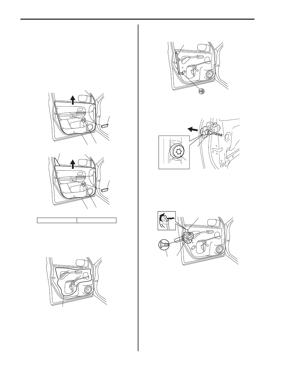
Removal
1) Remove door mirror trim (1), front door inner garnish
(2) (3 door model only) and door trim screw cover
(3).
2) Remove door trim (4) after removing door trim screw
(5) and clips.
3) Disconnect door illumination lamp lead wire and
power window switch and mirror switch lead wire at
coupler.
4) Remove door sealing cover (1).
5) Raise window all the way up.
6) Remove door sash (1).
7) Remove key cylinder mounting bolt (1), and then
remove key cylinder (2).
8) Disconnect door opening control rod (1) from outside
handle.
9) Disconnect door lock motor lead wire at coupler.
10) Remove door latch screws (2) and remove door lock
assembly (3).
[A]: 5 door model
[B]: 3 door model
1
3
5
4
2
1
3
5
4
[A]
[B]
I5JB0A950010-01
1
I5JB0A950011-02
1
I5JB0A960003-01
1
2
I4RS0B960005-01
3
2
1
I5JB0A960004-01
Security and Locks: 9F-6
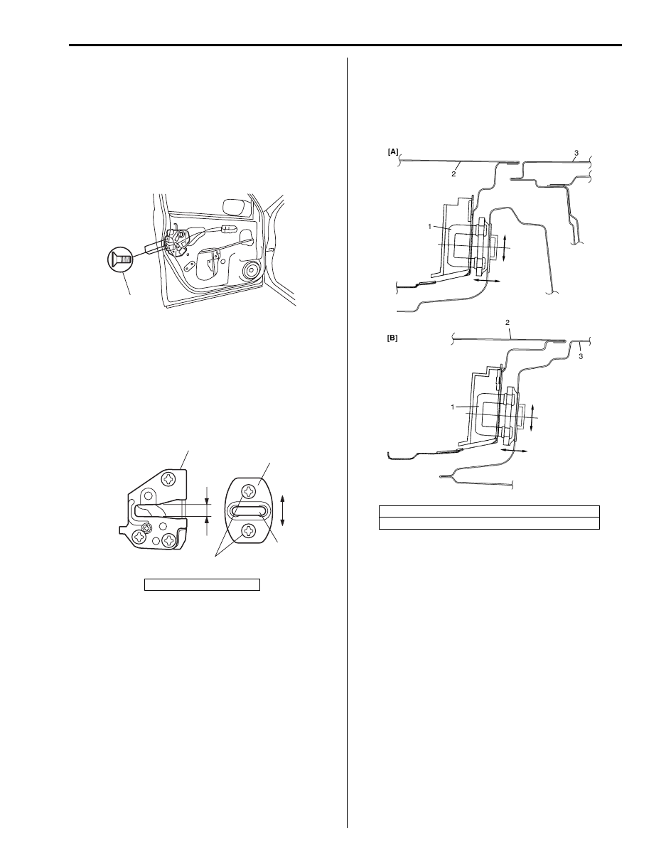
Installation
Reverse removal procedure to install front door lock
assembly noting the following instructions.
• Apply grease to sliding parts of door latch assembly.
: Grease 99000–25010 (SUZUKI Super Grease A)
• Tighten door latch screws to specified torque.
Tightening torque
Door latch screw (a): 5.0 N·m (0.5 kgf-m, 4.0 lb-ft)
• Move door latch striker (2) up or down so its center
aligns with the center of groove “A” on the door lock
assembly (1) as shown.
Striker should be moved vertically and placed level.
Do not adjust door lock.
Tightening torque
Door latch striker screw (a): 10 N·m (1.0 kgf-m, 7.5
lb-ft)
• Move door latch striker (1) sideways to adjust door
outer panel surface (2) flush with rear door outer
panel or body outer panel surface (3) as shown.
In order to correctly obtain door lock operation
increase or decrease number of shims inserted
between body and striker (1) to adjust it.
Front Door Lock Assembly Inspection
S5JB0A9606003
• Check that door open and closes smoothly and
properly.
• Check that door stops in the secondary latched
position properly (preventing door from opening
freely) and that door closed completely in the fully
latched position.
• Adjust door latch striker position, if necessary.
3. Shaft
(a)
I5JB0A960005-01
1
2
3
(a)
“A”
I5JB0A960006-01
[A]: Front door (5 door model)
[B]: Rear door (5 door model) or front door (3 door model)
I3RM0A960013-01

9F-7 Security and Locks:
Power Door Lock Switch Inspection
S5JB0A9606004
Check for continuity between terminals at each switch
position. If check result is not as specified, replace
switch.
Door Key Cylinder Switch Inspection
S5JB0A9606005
1) Remove front door trim referring to Step 1) to 3) of
“Front Door Glass Removal and Installation in
Section 9E”
2) Check for continuity between terminals at each
switch position. If check result is not as specified,
replace door lock assembly.
Power Door Lock Actuator Inspection (If
Equipped)
S5JB0A9606006
NOTE
If rear end door is closed and the rear end
door lock actuator does not function in
unlock position, follows the procedures to
unlock the rear end door lock actuator.
1. Remove cap (1).
2. Penetrate door sealing cover (2) by jack
lever (3) or whatever to insert jack lever,
and push emergency lever (4) into unlock
position “a”.
3. After inspection replace door sealing
cover.
1) Remove door trim from door panel.
For front door, refer to Step 1) to 3) of “Front Door
Glass Removal and Installation in Section 9E”.
For rear door, refer to Step 1) to 3) of “Rear Door
Glass Removal and Installation in Section 9E”.
For rear end door, refer to Step 1) of “Rear End Door
Assembly Removal and Installation in Section 9J”.
2) Disconnect power door lock actuator coupler.
3) Connect battery positive (+) and negative (–)
terminals to the door lock actuator terminals (a, b, c,
d) as shown in figure.
If it does not operate as specified in the following
table, replace door lock assembly.
1. Power door lock switch
I5JB0A960007-01
a
b
c
d
e
f
LOCK
OFF
UNLOCK
d
a
b
c
f
e
Right side switch terminals
Left side switch terminals
I5JB0A960008-01
2
3
1
4
“a”
I5JB0A960022-01

Security and Locks: 9F-8
For front door
For rear door
[A]: Without deadlock
[B]: With deadlock
[A]
[B]
a
b
c
d
e
f
Right side switch terminals
b
a
c
Lock
Unlock
Unlock
Lock
Deadlock
Unlock
Left side switch terminals
d
c
a
Deadlock
Lock
d
b
Lock
Unlock
f
e
Terminals
Lock
Unlock
Unlock
Lock
Terminals
d
a
Lock
Unlock
f
e
Terminals
I5JB0A960009-02
[A]: Without deadlock
[B]: With deadlock
[A]
[B]
a
b
c
d
e
f
g
h
Lock
Unlock
g
h
e
f
Right side switch terminals
Left side switch terminals
Right side switch terminals
d
c
a
Lock
Unlock
Unlock
Lock
Deadlock
Lock
Left side switch terminals
b
a
c
Deadlock
Lock
b
d
Lock
Unlock
Unlock
Lock
Terminals
d
a
Lock
Unlock
f
g
Terminals
I5JB0A960010-01
Нет комментариевНе стесняйтесь поделиться с нами вашим ценным мнением.
Текст