Suzuki Grand Vitara JB416 / JB420. Manual — part 198
4A-9 Brake Control System and Diagnosis:
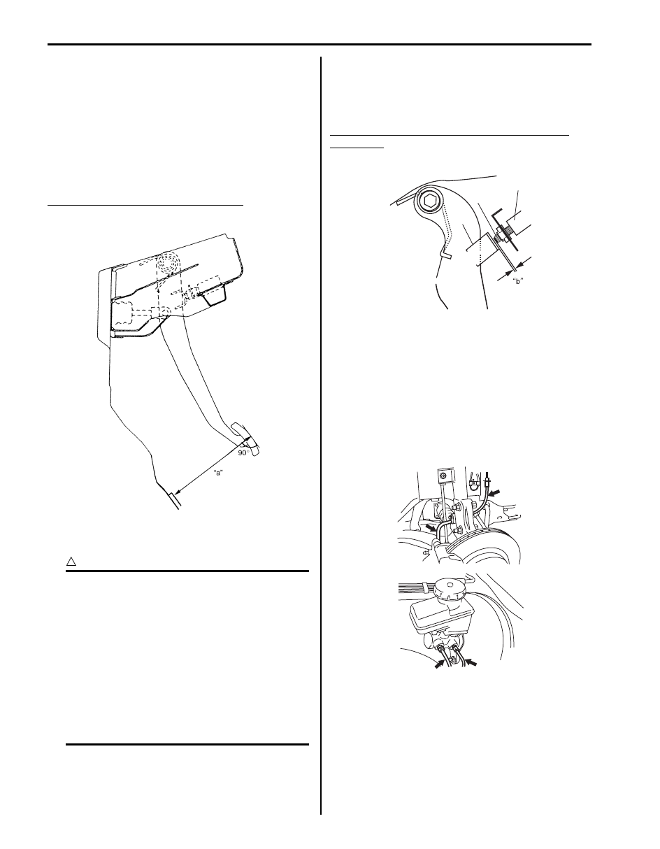
Brake Pedal Free Height Adjustment
S5JB0A4106005
Measure brake pedal free height between pedal and
carpet installed on dash panel.
If the measurement is not within the specification, check
the position of booster push rod clevis and/or brake light
switch, referring to, “Master Cylinder Assembly
Inspection”, “Booster Push Rod Clevis Adjustment” and/
or “Brake Light Switch Adjustment”. The free height
varies depending on installation position of booster push
rod clevis and stop light switch.
Brake pedal free height “a” from carpet
“a”: 131 – 141 mm (5.16 – 5.55 in.)
Brake Light Switch Adjustment
S5JB0A4106006
CAUTION
!
Do not apply any oil or grease (including rust
preventives, lubricant, etc.) to following
sections.
* Stop light switch (1) (including its tip end)
* Switch (1) contacting section of brake pedal
stay (3)
Oil or grease, if applied, will enter the contact
point in the switch, causing contact failure.
Also, when checking, adjusting or replacing
brake switch, check that no oil or grease is
attached to switch contacting section on
brake pedal side or tip end of switch.
Wipe off oil or grease being attached.
Adjustment should be made as follows when installing
switch (1). Pull up brake pedal toward you and while
holding it there, adjust switch position so that clearance
between end of switch thread (2) and brake pedal stay
(3).
Clearance “b” between end of thread and brake
pedal stay
“b”: 1.5 – 2.5 mm (0.06 – 0.10 in.)
Brake Flexible Hose and Pipe Check
S5JB0A4106007
The brake hose assembly should be checked for road
hazard damage, for cracks and chafing of the flexible
hose, for leaks and blisters. A light and mirror may be
needed for an adequate inspection. If any of the above
conditions are observed on the brake flexible hose, it is
necessary to replace it.
Inspect the pipe for damage, cracks, dents and
corrosion. If any defect is found, replace it.
IYSQ01410007-01
3
2
1
I3JA01410004-01
I5JB0A410007-01

Brake Control System and Diagnosis: 4A-10
Master Cylinder Check
S5JB0A4106008
Check for a cracked master cylinder casting or brake
fluid around the master cylinder. Leaks are indicated
only if there is at least a drop of fluid. A damp condition is
not abnormal.
Flushing Brake Hydraulic System
S5JB0A4106009
It is recommended that entire hydraulic system be
thoroughly flushed with clean brake fluid whenever new
parts are installed in hydraulic system.
Periodical change of brake fluid is also recommended.
Booster Operation Check
S5JB0A4106010
There are two ways to perform this inspection, with and
without a tester. Ordinarily, it is possible to roughly
determine its condition without using a tester.
NOTE
For this check, make sure that no air is in
hydraulic line.
Inspection without Tester
Check air tightness
1) Start engine.
2) Stop engine after running for 1 to 2 minutes.
3) Depress brake pedal several times with the same
load as in ordinary braking and observe pedal travel.
If pedal goes down deep the first time but its travel
decreases as it is depressed the second and more
times, air tightness is obtained.
4) If pedal travel doesn’t change, air tightness isn’t
obtained.
NOTE
If defective, inspect vacuum lines and sealing
parts, and replace any faulty part.
When this has been done, repeat the entire
test.
Check operation
1) With engine stopped, depress brake pedal several
times with the same load and make sure that pedal
travel doesn’t change.
2) Start engine while depressing brake pedal. If pedal
travel increases a little, operation is satisfactory. But
no change in pedal travel indicates malfunction.
[A]: Good
2. 2nd
1. 1st
3. 3rd
I5JB0A410005-01
I5JB0A410008-01
[B]: No Good
1. 1st, 2nd, 3rd
I5JB0A410009-01
IYSQ01410018-01
IYSQ01410019-01

4A-11 Brake Control System and Diagnosis:
Check air tightness under load
1) With engine running, depress brake pedal. Then
stop engine while holding brake pedal depressed.
2) Hold brake pedal depressed for 30 seconds. If pedal
height does not change, condition is good. But it isn’t
if pedal rises.
Front Brake Hose / Pipe Removal and
Installation
S5JB0A4106011
CAUTION
!
Do not allow brake fluid to get on painted
surfaces. Painted surfaces will be damaged
by brake fluid, flush it with water immediately
if any fluid is spilled.
Removal
1) Raise and support vehicle properly. Remove tire and
wheel.
NOTE
This operation is not necessary when
removing pipes connecting master cylinder.
2) Clean dirt and foreign material from both flexible
hose end and pipe end fittings.
3) Drain brake fluid in reservoir.
4) Remove brake flexible hose or pipe.
Installation
Reverse brake flexible hose removal procedure, noting
the following.
• Make sure that steering wheel is in straight-forward
position and flexible hose has not twist or kink.
• Check to make sure that flexible hose doesn’t contact
any part of suspension, both in extreme right and
extreme left turn conditions.
If it does at any point, remove and correct. Fill and
maintain brake fluid level in reservoir.
• Bleed brake system. Refer to “Air Bleeding of Brake
• Perform brake test and check installed part for fluid
leakage.
Rear Brake Hose / Pipe Removal and
Installation
S5JB0A4106012
CAUTION
!
Do not allow brake fluid to get on painted
surfaces. Painted surfaces will be damaged
by brake fluid, flush it with water immediately
if any fluid is spilled.
Removal
1) Raise and support vehicle properly. Remove tire and
wheel.
2) Clean dirt and foreign material from both flexible
hose end and pipe end fittings.
3) Drain brake fluid in reservoir.
4) Remove brake flexible hose or pipe.
Installation
Reverse brake flexible hose removal procedure, noting
the following.
• Fill and maintain brake fluid level in reservoir.
• Bleed brake system. Refer to “Air Bleeding of Brake
• Perform brake test and check each installed part for
fluid leakage.
• Install clamps properly referring to the figure and
tighten bolts.
• When installing hose, make sure that it has no twist or
kink.
IYSQ01410020-01
IYSQ01410021-01

Brake Control System and Diagnosis: 4A-12
Master Cylinder Components
S5JB0A4106026
CAUTION
!
Never disassemble master cylinder. Disassembly will spoil its original function. If faulty condition is
found, replace it with new one as an assembly.
[A]
[B]
4
5
3
3
2
2
1
7
6
8
(a)
I5JB0A410010-01
[A]: A/T vehicle
2. Grommet
: Apply brake fluid.
5. Filter
8. Master cylinder fixing nut
[B]: M/T vehicle
3. Reservoir
6. Reservoir connector pin
: 18 N
⋅m (1.8 kgf-m, 13.0 lb-ft)
1. Master cylinder body
4. Reservoir cap
7. O-ring
: Do not reuse.
Нет комментариевНе стесняйтесь поделиться с нами вашим ценным мнением.
Текст