Suzuki Grand Vitara JB416 / JB420. Manual — part 199

4A-13 Brake Control System and Diagnosis:
Master Cylinder Reservoir Removal and
Installation
S5JB0A4106013
CAUTION
!
Do not allow brake fluid to get on painted
surfaces. Painted surfaces will be damaged
by brake fluid, flush it with water immediately
if any fluid is spilled.
Removal
1) Disconnect reservoir lead wire at coupler (1).
2) Clean outside of reservoir (2) and master cylinder
(3).
3) Take out fluid with syringe or such.
4) Disconnect clutch reservoir hose (1) from reservoir
(2) for M/T vehicle.
5) Remove reservoir connector pin (1) by using special
tool and then reservoir.
Special tool
(A): 09916–44310
Installation
1) When using new grommets (3), lubricate them with
the same fluid as the one to fill reservoir (1) with.
Then press-fit grommets (3) to master cylinder (2).
Grommets (3) must be seated in place.
2) Install reservoir (1) and drive in reservoir connector
pin (2) by using special tool (A). till both of its ends at
the right and left of reservoir becomes the same
length.
Special tool
(A): 09916–44310
3) Connect clutch reservoir hose (1) to reservoir (2) for
M/T vehicle.
3
2
1
I5JB0A410011-02
2
1
I5JB0A410012-02
1
(A)
I5JB0A410013-02
1
2
3
3
I5JB0A410014-01
I5JB0A410015-01
2
1
I5JB0A410012-02

Brake Control System and Diagnosis: 4A-14
4) Connect reservoir lead wire at coupler.
5) Fill reservoir with specified fluid.
6) After installing, bleed air from brake system referring
to “Air Bleeding of Brake System” and at the same
time bleed air from clutch system referring to “Air
Bleeding of Clutch System in Section 5C” for M/T
vehicle.
7) Upon completion of installation, check for fluid
leakage.
Master Cylinder Assembly Removal and
Installation
S5JB0A4106014
CAUTION
!
• Never disassemble master cylinder.
Disassembly will spoil its original function.
If faulty condition is found, replace it with
new one as an assembly.
• Do not allow brake fluid to get on painted
surfaces. Painted surfaces will be
damaged by brake fluid, flush it with water
immediately if any fluid is spilled.
Removal
1) Disconnect reservoir lead wire at coupler (1).
2) Clean outside of master cylinder and take out fluid
with syringe or such.
3) Disconnect clutch reservoir hose (1) from reservoir
(2) for M/T vehicle.
4) Loosen brake pipe flare nuts (2) for master cylinder
(1).
5) Disconnect brake pipes (3) from master cylinder (1).
6) Loosen master cylinder fixing nuts (1) and then
remove master cylinder (2) with reservoir (3) from
brake booster (4).
Installation
1) Install new master cylinder O-ring (1) to master
cylinder.
2) Install master cylinder (2) with reservoir (3) to brake
booster (4).
1
I5JB0A410016-02
2
1
I5JB0A410012-02
2
3
3
1
I5JB0A410017-01
1
2
1
3
4
I5JB0A410018-02
1
2
3
4
I5JB0A410019-01

4A-15 Brake Control System and Diagnosis:
3) Tighten master cylinder fixing nuts (1) to specified
torque.
Tightening torque
Master cylinder fixing nut (a): 18 N·m (1.8 kgf-
m, 13.0 lb-ft)
4) Connect brake pipes to master cylinder and tighten
brake pipe flare nuts (1) to specified torque.
Tightening torque
Brake pipe flare nut (a): 16 N·m (1.6 kgf-m, 12.0
lb-ft)
5) Connect clutch reservoir hose (1) to reservoir (2) for
M/T vehicle.
6) Connect reservoir lead wire at coupler.
7) Fill reservoir with specified brake fluid.
8) After installing, bleed air from brake system referring
to “Air Bleeding of Brake System” and at the same
time bleed air from clutch system referring to “Air
Bleeding of Clutch System in Section 5C” for M/T
vehicle.
9) Perform brake test and check each installed part for
fluid leakage.
Master Cylinder Assembly Inspection
S5JB0A4106017
• Check master cylinder for corrosion and smooth
operation.
• Inspect distance “a” to be the following.
If measurement is out of specification, replace master
cylinder assembly.
Distance
“a”: 72.0 mm (2.83 in.) or more
1,(a)
1,(a)
I5JB0A410021-02
1,(a)
I5JB0A410020-01
2
1
I5JB0A410012-02
I5JB0A410022-01
Brake Control System and Diagnosis: 4A-16
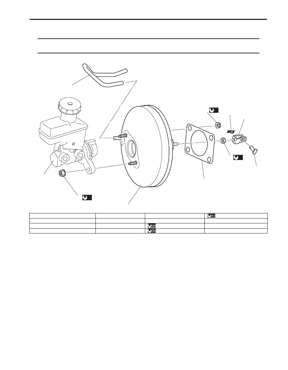
Brake Booster Components
S5JB0A4106018
NOTE
The difference between RH steering vehicle and LH steering vehicle booster components is the
location of vacuum hose.
1
2
3
4
5
6
7
8
9
10
(a)
(b)
(c)
I5JB0A410023-02
1. Brake master cylinder assembly
5. Clevis pin lock nut
9. Brake vacuum hose
: 26 N
⋅m (2.6 kgf-m, 19.0 lb-ft)
2. Brake booster assembly
6. Clevis pin
10. Master cylinder fixing nut
3. Gasket
7. Clip
: 18 N
⋅m (1.8 kgf-m, 13.0 lb-ft)
4. Push rod clevis
8. Booster attaching nut
: 13 N
⋅m (1.3 kgf-m, 9.5 lb-ft)
Нет комментариевНе стесняйтесь поделиться с нами вашим ценным мнением.
Текст