Suzuki Grand Vitara JB416 / JB420. Manual — part 238

5A-86 Automatic Transmission/Transaxle:
4) Pass and connect interlock cable as shown in the figure.
5) Pull out lock button (1) of selector side cable end (2).
6) Shift selector lever to “N” position.
7) Install cable casing cap (3) to selector bracket (4).
8) Connect cable end (1) to interlock cam (2) with
ignition switch turned to “ACC” position.
9) Drive lock button (5) in cable end until it locks cable
expansion and contraction.
10) Install steering column cover.
11) If the vehicle is equipped with air bag system,
connect negative cable at battery and enable air bag
system, referring to “Enabling Air Bag System in
Section 8B”.
I5JB0A510065-02
1-1. Interlock cable for LH steering vehicle
2-1. Key cylinder for LH steering vehicle
1-2. Interlock cable for RH steering vehicle
2-2. Key cylinder for RH steering vehicle
1
2
I5JB0A510066-01
4
5
3
2
1
I5JB0A510067-01

Automatic Transmission/Transaxle: 5A-87
Brake and key Interlock System Inspection
S5JB0A5106052
1) Check that selector lever cannot be moved to any
other range from “P” range position when ignition
switch key is at ACC position, at LOCK position or it
is removed from keyhole of ignition switch, or brake
pedal is not depressed.
2) Shift select lever to “P” range position, release knob
button and check for the following.
• Ignition key can be turned between LOCK and
ACC positions back and forth and also it can be
removed from ignition switch.
• With shift lock solenoid release button (1) pushed
and ignition key turned to ACC position, selector
lever can be shifted from “P” range position to any
other range.
• For LH steering vehicle, remove manual release
button hole cover (1). With shift lock solenoid
release button pushed by key or flat end rod and
ignition key turned to LOCK position, selector
lever can not be shifted from “P” range position to
any other range.
• For RH steering vehicle, with shift lock solenoid
release button (1) pushed and ignition key turned
to LOCK position, selector lever can not be shifted
from “P” range position to any other range.
• When ignition switch is turned ON and brake
pedal is depressed, selector lever can be shifted
from “P” range position to any other range.
3) With ignition lever shifted to any position other than
“P” range, check that ignition key cannot be turned
LOCK position and it cannot be removed from
ignition switch unless it is at LOCK position.
I5JB0A510165-01
I5JB0A510166-01
1
I5JB0A510167-01
1
I5JB0A510168-01
I5JB0A510169-01
I5JB0A510170-01

5A-88 Automatic Transmission/Transaxle:
Mode Select Switch Inspection
S5JB0A5106053
1) Pull out mode select switch from front center console
box.
2) Disconnect mode select switch connector.
3) Check continuity between mode select switch
terminals.
Mode select switch specification
Input Shaft Speed Sensor Removal and
Installation
S5JB0A5106054
Removal
1) Disconnect negative cable at battery.
2) Hoist vehicle.
3) Disconnect input shaft speed sensor connector.
4) Remove input shaft speed sensor (1) from
transmission.
Installation
1) Check that sensor is free from any metal particles
and damage.
2) Apply A/T fluid to new O-ring and then install input
shaft speed sensor (1) to transmission.
Tighten sensor bolt to specified torque.
Tightening torque
Input shaft speed sensor bolt (a): 7 N·m (0.7 kgf-
m, 5.0 lb-ft)
3) Connect input shaft speed sensor connector.
4) Lower hoist.
5) Connect negative cable at battery.
Mode select
switch
Normal position Power position
Continuity
No continuity
Continuity
A: Push
B: Push again to release
B
A
I5JB0A510042-01
1
I5JB0A510043-01
1
(a)
I5JB0A510044-01
Automatic Transmission/Transaxle: 5A-89
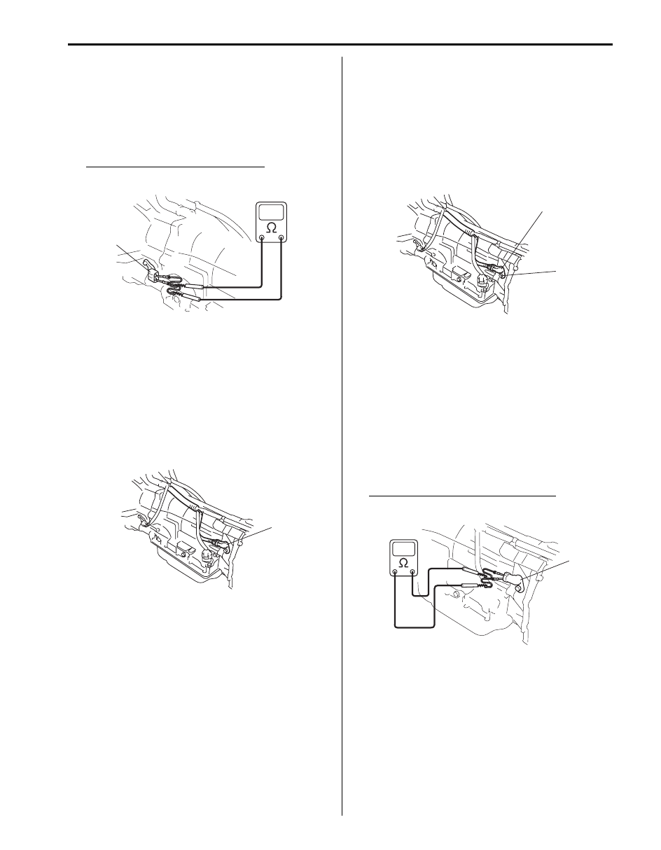
Input Shaft Speed Sensor Inspection
S5JB0A5106055
1) Disconnect negative cable at battery.
2) Hoist vehicle.
3) Disconnect input shaft speed sensor connector.
4) Check input shaft speed sensor (1) for resistance
between terminals of sensor.
Input shaft speed sensor resistance
Standard: 560 – 680
Ω (at 20 °C (68 °F))
Output Shaft Speed Sensor Removal and
Installation
S5JB0A5106056
Removal
1) Disconnect negative cable at battery.
2) Hoist vehicle.
3) Disconnect output shaft speed sensor connector.
4) Remove output shaft speed sensor (1) from
transmission.
Installation
1) Check that sensor is free from any metal particles
and damage.
2) Apply A/T fluid to new O-ring and then install output
shaft speed sensor (1) to transmission.
Tighten sensor bolt to specified torque.
Tightening torque
Output shaft speed sensor bolt (a): 7 N·m (0.7
kgf-m, 5.0 lb-ft)
3) Connect output shaft speed sensor connector.
4) Lower hoist.
5) Connect negative cable at battery.
Output Shaft Speed Sensor Inspection
S5JB0A5106057
1) Disconnect negative cable at battery.
2) Hoist vehicle.
3) Disconnect output shaft speed sensor connector.
4) Check output shaft speed sensor (1) for resistance
between terminals of sensor.
Output shaft speed sensor resistance
Standard: 560 – 680
Ω (at 20 °C (68 °F))
1
I5JB0A510045-01
1
I5JB0A510048-01
1
(a)
I5JB0A510049-01
1
I5JB0A510050-01
Нет комментариевНе стесняйтесь поделиться с нами вашим ценным мнением.
Текст