Suzuki Grand Vitara JB416 / JB420. Manual — part 108
1D-100 Engine Mechanical: For J20 Engine
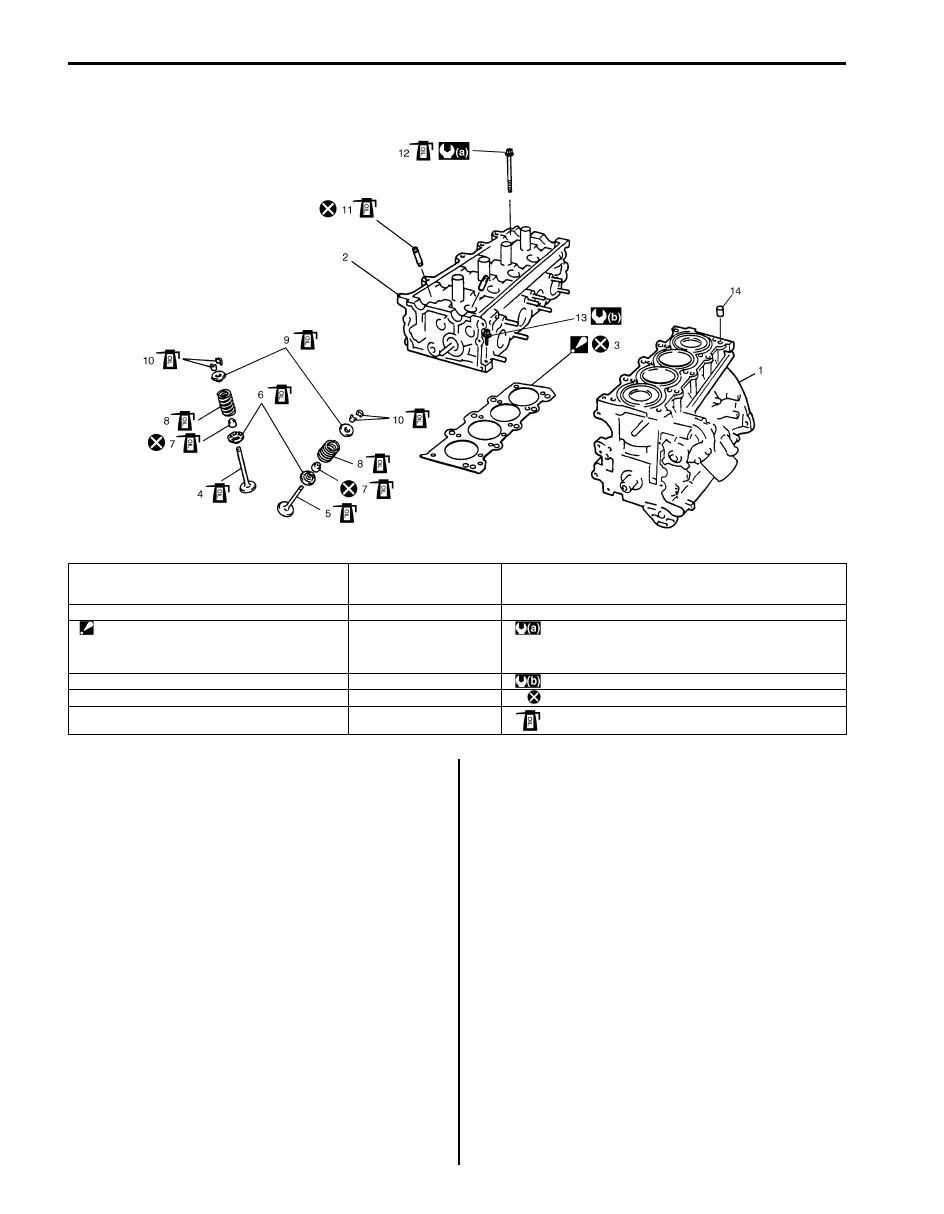
Valves and Cylinder Head Components
S5JB0A1426032
Valves and Cylinder Head Removal and
Installation
S5JB0A1426033
Removal
1) Remove engine assembly from vehicle referring to
“Engine Assembly Removal and Installation: For J20
Engine”.
2) Remove oil pan referring to “Oil Pan and Oil Pump
Strainer Removal and Installation: For J20 Engine in
Section 1E”.
3) Remove cylinder head cover referring to “Cylinder
Head Cover Removal and Installation: For J20
Engine”.
4) Remove timing chain cover. Refer to “Timing Chain
Cover Removal and Installation: For J20 Engine” for
removal.
5) Remove 2nd timing chain and 1st timing chain. Refer
to “2nd Timing Chain and Chain Tensioner Removal
and Installation: For J20 Engine” and “1st Timing
Chain and Chain Tensioner Removal and
Installation: For J20 Engine” for removal.
6) Remove camshafts, tappets and shims. Refer to
“Camshafts, Tappet and Shim Removal and
Installation: For J20 Engine” for removal.
I5JB0A142039-01
1. Cylinder block
7. Valve stem seal
13. Cylinder head bolt (M6)
: Be sure to tighten cylinder head bolt (M8) after securing
cylinder head bolt (M10).
2. Cylinder head
8. Valve spring
14. Knock pin
3. Cylinder head gasket
: Identification number provided on gasket comes
to crankshaft pully side, facing up.
9. Valve spring retainer
: Tighten 52 N
⋅m (5.2 kgf-m, 38.0 lb-ft), 82 N⋅m (8.2 kgf-m, 59.5
lb-ft), 0 N
⋅m (0 kgf-m, 0 lb-ft), 52 N⋅m (5.2 kgf-m, 38.0 lb-ft)
and 103 N
⋅m (10.3 kgf-m, 74.5 lb-ft) by the specified
procedure.
4. Intake valve
10. Valve cotter
: 11 N
⋅m (1.1 kgf-m, 8.0 lb-ft)
5. Exhaust valve
11. Valve guide
: Do not reuse.
6. Valve spring seat
12. Cylinder head bolt (M10)
: Apply engine oil to sliding surface of each part.
Engine Mechanical: For J20 Engine 1D-101
7) Loosen cylinder head bolts (M10) in such order as
numbered in figure and remove them.
NOTE
Don’t forget to remove cylinder head bolt
(M6) (3) as shown in figure.
8) Check all around cylinder head for any other parts
required to be removed or disconnected and remove
or disconnect whatever necessary.
9) Remove cylinder head with intake manifold, exhaust
manifold and water outlet cap. Use lifting device, if
necessary.
Installation
1) Match match mark (1) on crank timing sprocket and
mating surface (2) of cylinder block and lower
crankcase.
2) Clean mating surface of cylinder head and cylinder
block (2). Remove oil, old gasket and dust from
mating surface.
3) Install knock pins (3) to cylinder block.
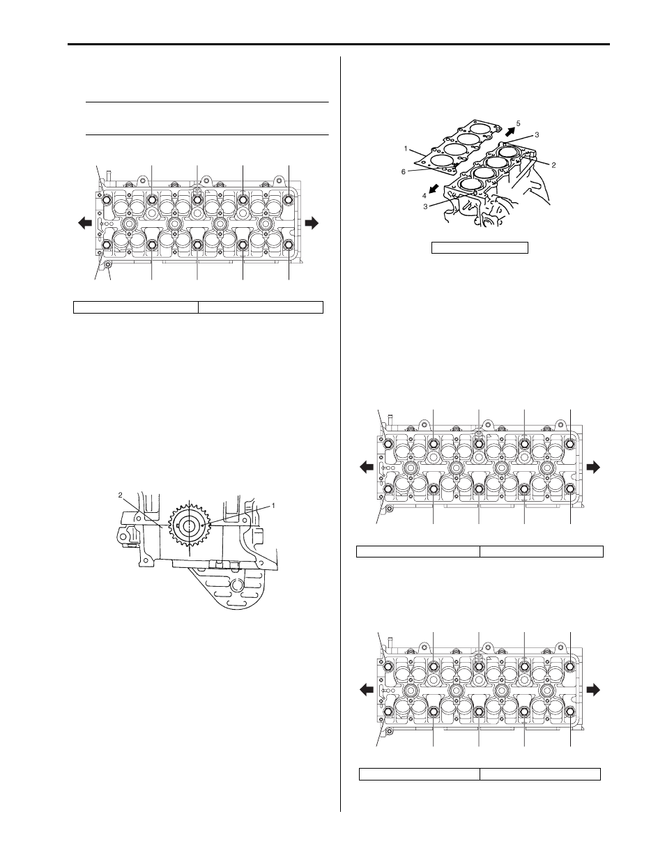
4) Install new cylinder head gasket (1) to cylinder block.
Identification number (6) provided on gasket comes
to crankshaft pulley side (4), facing up (toward
cylinder head side).
5) Install cylinder head to cylinder block.
Apply engine oil to cylinder head bolts and tighten
them gradually as follows.
a) Tighten cylinder head bolts (M10) to 52 N
⋅m (5.2
kgf-m, 38.0 lb-ft) according to numerical order in
figure.
b) In the same manner as in step a), retighten
cylinder head bolts (M10) to 82 N
⋅m (8.2 kgf-m,
59.5 lb-ft).
c) Loosen cylinder head bolts (M10) until tightening
torque is reduced to 0 according to numerical
order in figure.
1. Crankshaft pulley side
2. Flywheel side
“5”
“4”
“8”
“10”
“6”
“2”
3, “1”
“9”
“11”
“7”
“3”
1
2
I5JB0A142040-02
I2RH01140118-01
5. Flywheel side
1. Crankshaft pulley side
2. Flywheel side
1. Crankshaft pulley side
2. Flywheel side
I5JB0A142041-01
“7”
“9”
“4”
“2”
“6”
“8”
“5”
“1”
“3”
“10”
1
2
I5JB0A142042-01
“4”
“3”
“7”
“9”
“5”
“1”
“8”
“10”
“6”
“2”
1
2
I5JB0A142043-01

1D-102 Engine Mechanical: For J20 Engine
d) Tighten cylinder head bolts (M10) to 52 N
⋅m (5.2
kgf-m, 38.0 lb-ft) according to numerical order in
figure.
e) In the same manner as in step b), retighten
cylinder head bolts (M10) to 103 N
⋅m (10.3 kgf-
m, 74.5 lb-ft).
f) Tighten cylinder head bolt (M6) to specified
torque.
Tightening torque
Cylinder head bolt (M10) (a): Tighten 52 N
⋅m
(5.2 kgf-m, 38.0 lb-ft), 82 N
⋅m (8.2 kgf-m, 59.5
lb-ft), 0 N
⋅m (0 kgf-m, 0 lb-ft), 52 N⋅m (5.2 kgf-
m, 38.0 lb-ft) and 103 N
⋅m (10.3 kgf-m, 74.5 lb-
ft) by the specified procedure.
Cylinder head bolt (M6) (b): 11 N·m (1.1 kgf-
m, 8.0 lb-ft)
6) Install camshafts and tappets and shims. Refer to
“Camshafts, Tappet and Shim Removal and
Installation: For J20 Engine” for installation.
7) Install 1st timing chain. Refer to “1st Timing Chain
and Chain Tensioner Removal and Installation: For
J20 Engine” for installation.
8) Install 2nd timing chain. Refer to “2nd Timing Chain
and Chain Tensioner Removal and Installation: For
J20 Engine” for installation.
9) Install timing chain cover. Refer to “Timing Chain
Cover Removal and Installation: For J20 Engine” for
installation.
10) Check intake and exhaust valve lashes referring to
“Valve Lash (Clearance) Inspection: For J20
Engine”.
11) Install cylinder head cover referring to “Cylinder
Head Cover Removal and Installation: For J20
Engine”.
12) Install oil pan referring to “Oil Pan and Oil Pump
Strainer Removal and Installation: For J20 Engine in
Section 1E”.
13) Install engine assembly to vehicle referring to
“Engine Assembly Removal and Installation: For J20
Engine”.
Valves and Cylinder Head Disassembly and
Assembly
S5JB0A1426034
Disassembly
1) When servicing cylinder head, remove intake
manifold, injectors, exhaust manifold and water
outlet cap from cylinder head.
2) Using special tools, compress valve springs and
then remove valve cotters (1) also by using special
tool.
Special tool
(A): 09916–14510
(B): 09916–16510
(C): 09919–28610
(D): 09916–84511
1. Crankshaft pulley side
2. Flywheel side
“7”, (a)
“9”, (a) 3, “11”, (b) “4”, (a)
“2”, (a)
“6”, (a)
“8”, (a)
“5”, (a)
“1”, (a)
“3”, (a)
“10”, (a)
I5JB0A142044-02
I5JB0A142045-01

Engine Mechanical: For J20 Engine 1D-103
3) Release special tool, and remove spring retainers
and valve springs.
4) Remove valve from combustion chamber side.
5) Remove valve stem seal (1) from valve guide, and
then valve spring seat (2).
NOTE
Do not reuse seal once disassembled. Be
sure to use new seal when assembling.
6) Using special tool (Valve guide remover), drive valve
guide out from combustion chamber side to valve
spring side.
Special tool
(A): 09916–46020
NOTE
Do not reuse valve guide once disassembled.
Be sure to use new valve guide (oversize)
when assembling.
7) Place disassembled parts except valve stem seal
and valve guide in order so that they can be installed
in their original positions.
Assembly
1) Before installing valve guide into cylinder head, ream
guide hole with special tool (11 mm reamer) so as to
remove burrs and make it truly round.
Special tool
(A): 09916–34542
(B): 09916–38210
2) Install valve guide to cylinder head.
Heat cylinder head uniformly at a temperature of 80
to 100
°C (176 to 212 °F) so that head will not be
distorted, and drive new valve guide into hole with
special tools.
Drive in new valve guide until special tool (Valve
guide installer) contacts cylinder head.
After installing, make sure that valve guide protrudes
by 13.0 mm (0.51 in.) from cylinder head.
Special tool
(A): 09916–57350
(B): 09916–57340
NOTE
• Do not reuse valve guide once
disassembled. Install new valve guide
(Oversize).
• Intake and exhaust valve guides are
identical.
Valve guide oversize
0.03 mm (0.0012 in.)
Valve guide protrusion “a” (In and Ex)
13.0 mm (0.51 in.)
I2RH01140125-01
I2RH01140126-01
I2RH01140127-01
I2RH01140128-01
Нет комментариевНе стесняйтесь поделиться с нами вашим ценным мнением.
Текст