Suzuki Grand Vitara JB416 / JB420. Manual — part 105
1D-88 Engine Mechanical: For J20 Engine
2nd Timing Chain and Chain Tensioner
Removal and Installation
S5JB0A1426024
CAUTION
!
After 2nd timing chain is removed, never turn
intake camshaft, exhaust camshaft and
crankshaft independently more than such an
extent as shown. If turned, interference may
occur between piston and valves and valves
themselves, and parts related to piston and
valves may be damaged.
Removal
1) Remove engine assembly from vehicle referring to
“Engine Assembly Removal and Installation: For J20
Engine”.
2) Remove oil pan. Refer to “Oil Pan and Oil Pump
Strainer Removal and Installation: For J20 Engine in
Section 1E” for removal.
3) Remove cylinder head cover. Refer to “Cylinder
Head Cover Removal and Installation: For J20
Engine” for removal.
4) Remove timing chain cover. Refer to “Timing Chain
Cover Removal and Installation: For J20 Engine” for
removal.
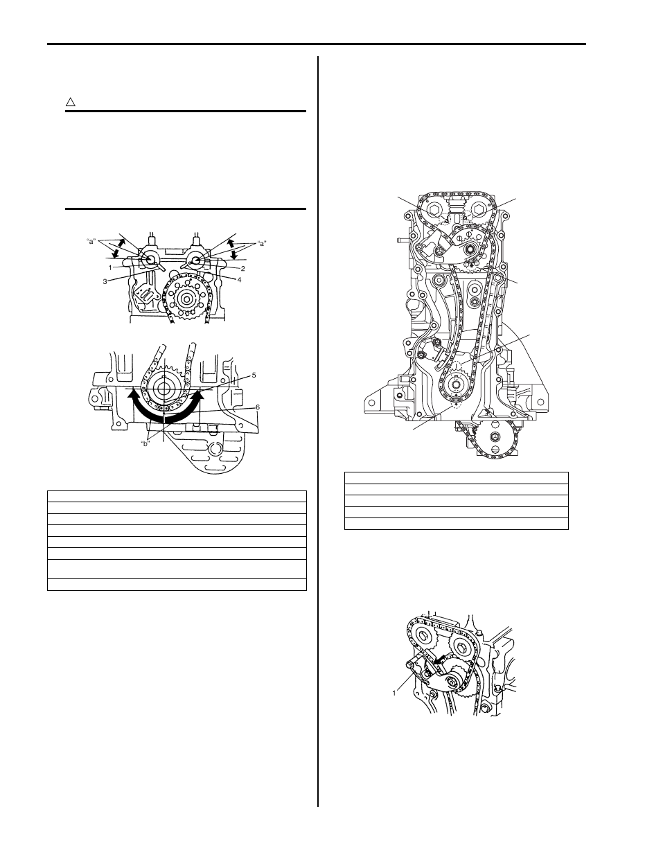
5) Turn crankshaft clockwise to meet the following
conditions.
• Key on crankshaft match with mark on cylinder
block (I).
• Arrow mark on idler sprocket points upward (II).
• Marks on cam sprockets match with marks on
cylinder head (III).
• Mark on crank sprocket match with mark on lower
crankcase (IV).
6) Remove timing chain tensioner adjuster No.2 (1) and
gasket. To remove them, slacken 2nd timing chain
by turning intake camshaft counterclockwise a little
while pushing back pad.
1. Knock pin of intake camshaft
2. Knock pin of exhaust camshaft
3. Timing mark of intake side
4. Timing mark of exhaust side
5. Match mark on crank timing sprocket
6. Timing mark on lower crankcase
“a”: Camshafts (IN & EX) allowable turning range. . Within 20
° on both
right and left
“b”: Crankshaft allowable turning range. . Within 90
° on both right and left
I5JB0A142060-01
1. Timing marks of intake camshaft timing sprocket
2. Timing marks of exhaust camshaft timing sprocket
3. Arrow mark on idler sprocket
4. Key on crankshaft
5. Timing mark of crankshaft timing sprocket
2, (III)
1, (III)
3, (II)
4, (I)
5, (IV)
I5JB0A142024-01
I2RH01140064-01

Engine Mechanical: For J20 Engine 1D-89
7) Remove intake and exhaust camshaft timing
sprocket bolts (1). To remove them, fit a spanner (4)
to hexagonal part (3) at the center of camshaft to
hold it stationary.
8) Remove camshaft timing sprockets and 2nd timing
chain (2).
Installation
1) Check that match mark (1) on crank timing sprocket
is in match with timing mark (2) on lower crankcase
as shown in figure.
2) Check that arrow mark (1) on idler sprocket faces
upward as shown in figure.
3) Check that knock pins of intake (2) and exhaust (3)
camshafts are aligned with timing marks on cylinder
head as shown in figure.
4) Install 2nd timing chain by aligning yellow plate (1) of
2nd timing chain and match marks on idler sprocket.
5) Install sprockets to intake and exhaust camshafts by
aligning dark blue plate of 2nd timing chain, match
marks on intake sprocket and exhaust sprocket
respectively.
CAUTION
!
Do not turn more than allowable turning
range.
If turned excessively, valve and piston may
be damaged.
NOTE
As an arrow mark is provided on both sides,
camshaft timing sprocket has no specific
installation direction.
4. Timing mark of intake side
5. Timing mark of exhaust side
I5JB0A142025-01
I2RH01140067-01
I2RH01140068-01
2. Match mark of 2nd timing chain (Arrow mark)
1. Dark blue
2. Arrow mark on intake camshaft timing sprocket
3. Arrow mark on exhaust camshaft timing sprocket
I2RH01140069-01
I2RH01140070-01

1D-90 Engine Mechanical: For J20 Engine
6) Tighten intake and exhaust camshaft timing sprocket
bolts (1) to specified torque. To tighten it, fit a
spanner (2) to hexagonal part (3) at the center of
camshaft to hold it stationary.
Tightening torque
Camshaft timing sprocket bolt (a): 80 N·m (8.0
kgf-m, 57.5 lb-ft)
7) Push back plunger (1) into tensioner body (2), and
hold it at the position by inserting stopper (3) into
body.
8) Install timing chain tensioner adjuster No.2 (1) with
new gasket.
Tightening torque
Timing chain tensioner adjuster No.2 bolt (a): 11
N·m (1.1 kgf-m, 8.0 lb-ft)
Timing chain tensioner adjuster No.2 nut (b): 45
N·m (4.5 kgf-m, 33.0 lb-ft)
9) Pull out stopper (2) from timing chain tensioner
adjuster No.2.
10) Turn crankshaft two rotations clockwise, and then
align timing mark (1) on crankshaft and timing mark
(2) on cylinder block as shown in figure.
At this time, check timing marks (3, 5 and 7) of
sprockets are in match with timing marks (4, 6 and 8)
of cylinder head, cylinder block and lower crank
case. Also, check arrow mark (9) on idler sprocket
faces upward as shown in figure.
11) Apply oil to timing chains, tensioner, tensioner
adjusters, sprockets and guides.
12) Install timing chain cover. Refer to “Timing Chain
Cover Removal and Installation: For J20 Engine” for
installation.
13) Install cylinder head cover. Refer to “Cylinder Head
Cover Removal and Installation: For J20 Engine” for
installation.
14) Install oil pan. Refer to “Oil Pan and Oil Pump
Strainer Removal and Installation: For J20 Engine in
Section 1E” for installation.
15) Install engine assembly to vehicle referring to
“Engine Assembly Removal and Installation: For J20
Engine”.
I5JB0A142061-01
I2RH01140072-01
I2RH01140073-01
3. Timing mark on crank timing sprocket
4. Timing mark on lower crankcase
5. Timing mark on intake camshaft timing sprocket
6. Timing mark of intake camshaft timing sprocket
7. Timing mark on exhaust camshaft timing sprocket
8. Timing mark of exhaust camshaft timing sprocket
9. Arrow mark on idler sprocket point upward
7
8
9
5
6
1
3
4
2
I5JB0A142026-01

Engine Mechanical: For J20 Engine 1D-91
2nd Timing Chain and Chain Tensioner
Inspection
S5JB0A1426025
Timing Chain Guide No.2
Check shoe (2) for wear or damage.
Camshaft Sprocket
Check teeth of sprocket for wear or damage.
Timing Chain
Check timing chain for wear or damage.
Tensioner Adjuster No.2
Check shoe (1) for wear or damage and latch functions
properly.
1st Timing Chain and Chain Tensioner Components
S5JB0A1426026
1. Timing chain guide No.2
I2RH01140075-01
I2RH01140076-01
I2RH01140077-01
I2RH01140078-01
OIL
(c)
10
(b)
9
(a)
8
4
7
OIL
3
OIL
1
OIL
2
OIL
5
6
I5JB0A142027-01
1. 1st timing chain
6. Timing chain tensioner adjuster No.1
: 25 N
⋅m (2.5 kgf-m, 18.0 lb-ft)
2. Idler sprocket
7. Timing chain guide No.1
: 9 N
⋅m (0.9 kgf-m, 6.5 lb-ft)
Нет комментариевНе стесняйтесь поделиться с нами вашим ценным мнением.
Текст