Suzuki Grand Vitara JB416 / JB420. Manual — part 41

1A-113 Engine General Information and Diagnosis:
DTC Detecting Condition and Trouble Area
DTC Confirmation Procedure
WARNING
!
• When performing a road test, select a place where there is no traffic or possibility of a traffic
accident and be very careful during testing to avoid occurrence of an accident.
• Road test should be carried out by 2 persons, a driver and a tester, on a level road.
NOTE
Check to make sure that following conditions are satisfied when using this “DTC Confirmation
Procedure”.
• Intake air temperature at engine start: –10
°C (14 °F) to 80 °C (176 °F)
• Intake air temperature: –10
°C (14 °F) to 70 °C (158 °F)
• Engine coolant temperature: 70
°C (158 °F) to 150 °C (302 °F)
• Altitude (barometric pressure): 2400 m, 8000 ft or less (560 mmHg, 75 kPa or more)
1) With ignition switch turned OFF, connect scan tool.
2) Turn ON ignition switch and print Freeze Frame Data or write them down using scan tool.
3) Clear DTC using scan tool.
4) Start engine and warm up to normal operating temperature.
5) Operate vehicle with condition as noted freeze frame data for 5 min.
6) Stop vehicle and check DTC and pending DTC.
DTC detecting condition
Trouble area
DTC P0171:
Total fuel trim (short term fuel trim + long term fuel trim) is higher
than specified range for 30 to 90 sec (depending on ECT)
continuously.
(2 driving cycle detection logic)
DTC P0172:
Total fuel trim (short term fuel trim + long term fuel trim) is lower
than specified range for 30 to 90 sec (depending on ECT)
continuously.
(2 driving cycle detection logic)
DTC P2195:
A/F sensor output is lower than specification while vehicle is
running constant speed and constant engine load after warmed
up.
(2 driving cycle detection logic)
DTC P2196:
A/F sensor output is higher than specification while vehicle is
running constant speed and constant engine load after warmed
up.
(2 driving cycle detection logic)
• Vacuum leakage
• Exhaust gas leakage
• Fuel pressure out of specification
• Fuel injector malfunction
• A/F sensor malfunction
• MAF sensor malfunction
• ECT sensor malfunction

Engine General Information and Diagnosis: 1A-114
DTC Troubleshooting
NOTE
Before this trouble shooting is performed, read the precautions for DTC troubleshooting referring to
“Precautions For DTC Troubleshooting”.
Step
Action
Yes
No
1
Was “Engine and Emission Control System Check”
performed?
Go to Step 2.
Go to “Engine and
Emission Control
System Check”.
2
Is there DTC(s) other than fuel system (DTC P0171 / P0172
/ 2195 / 2196)?
Go to applicable DTC
diag. flow.
Go to Step 3.
3
Intake system and exhaust system for leakage check
Are intake system and exhaust system in good condition?
Go to Step 4.
Repair or replace
defective part.
4
Fuel pressure check
1) Check fuel pressure referring to “Fuel Pressure Check”.
Is check result satisfactory?
Go to Step 5.
Repair or replace
defective part.
5
Fuel injectors and its circuit check
1) Check fuel injectors referring to “Fuel Injector Inspection
Is check result satisfactory?
Go to Step 6.
Faulty injector(s) or its
circuit.
6
Visual inspection
1) Check MAF sensor and air intake system.
• Objects which block measuring duct and resistor of
MAF sensor.
• Other air flow which does not pass MAF sensor.
Are they in good condition?
Go to Step 7.
Repair or replace
defective part.
7
MAF sensor for performance check
1) With ignition switch turned OFF, connect scan tool to
DLC.
2) Start engine and warm up to normal operating
temperature.
3) Check MAF value using scan tool (Refer to “Scan Tool
Data” for normal value.).
Is each value within specified range?
Go to Step 8.
Go to “DTC P0101:
Mass Air Flow Circuit
Range / Performance”.
8
ECT sensor for performance check
1) Check ECT sensor performance referring to Step 2 to 4
and 11 of “DTC P0116: Engine Coolant Temperature
Circuit Range / Performance”.
Is check result satisfactory?
Go to Step 9.
Faulty ECT sensor or its
circuit.

1A-115 Engine General Information and Diagnosis:
9
A/F sensor adjusting resistor power /ground circuit
check
1) Disconnect connector from A/F sensor with ignition
switch turned OFF.
2) Check for proper connection to A/F sensor connector.
3) If connections are OK, check A/F sensor adjusting
resistor circuit for the following.
• ECM 5 V power is applied to A/F sensor adjusting
resistor circuit at A/F sensor connector (power circuit
check)
• Resistance between ground to ECM for A/F sensor
adjusting resistor circuit and vehicle body ground is
less than 1
Ω at A/F sensor connector (ground circuit
check)
Is it in good condition?
Go to step 11.
Go to Step 10.
10 A/F sensor adjusting resistor circuit check
1) Disconnect connector from ECM with ignition switch
turned OFF.
2) Check for proper connection of each A/F sensor circuit
terminal to ECM connector.
3) If connections are OK, check A/F sensor adjusting
resistor circuit for the following.
• Resistance of each A/F sensor adjusting resistor
circuit wire between A/F sensor connector and ECM
connector is less than 3
Ω (continuity check)
• Resistance between A/F sensor adjusting resistor
circuit wires are infinity (no continuity check)
• Resistance between each A/F sensor adjusting
resistor circuit wire and vehicle body ground is infinity
(ground short check)
• Voltage between each A/F sensor adjusting resistor
circuit wire and vehicle body ground is 0 V with
ignition switch tuned ON (power short check)
Is it in good condition?
Substitute a known
good ECM and recheck.
Repair or replace
defective circuit.
11 A/F sensor adjusting resistor check
1) 1)Check for resistance of A/F sensor adjusting resistor
referring to “Air Fuel Ratio (A/F) Sensor On-Vehicle
Inspection in Section 1C”.
Is check result satisfactory?
Go to Step 12.
Replace A/F sensor.
12 A/F sensor for performance check
1) Check A/F sensor referring to Step 3 and 4 of “DTC
Is check result satisfactory?
Replace A/F sensor.
Repair or replace
defective circuit.
Step
Action
Yes
No
Engine General Information and Diagnosis: 1A-116
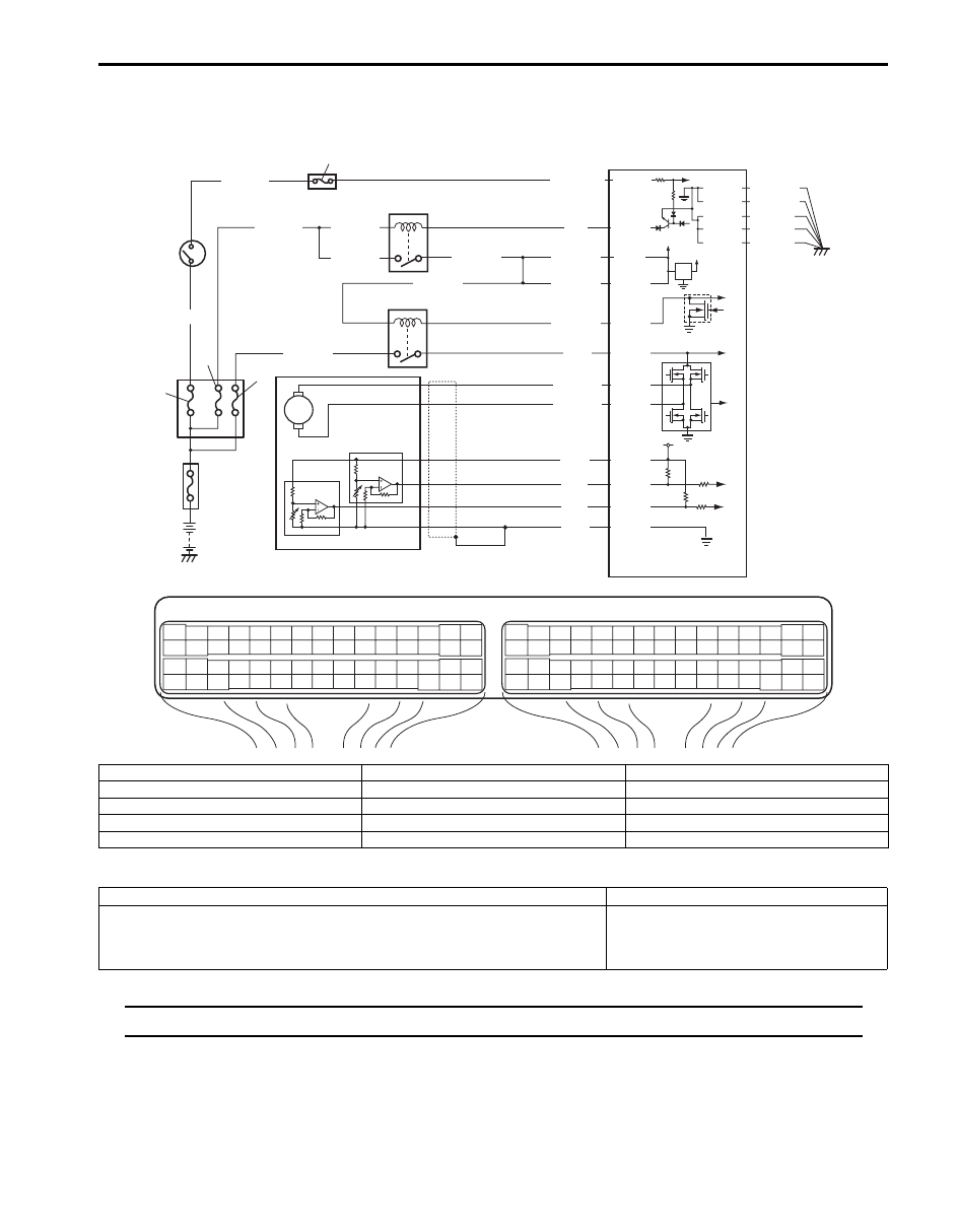
DTC P0222: Throttle Position Sensor (Sub) Circuit Low
S5JB0A1104075
Wiring Diagram
DTC Detecting Condition and Trouble Area
NOTE
When DTC P0122 and P0222 are indicated together, it is possible that “WHT” wire open circuit.
E23
C37
3
4
18
19
5
6
7
10
11
17
20
47
46
49
50
51
21
22
52
16
25
9
24
14
29
55
57
54 53
59
60
58
2
26
27
28
15
30
56
48
32
31
34
35
36
37
40
42
39 38
44
45
43
41
33
1
12
13
23
8
3
4
18
19
5
6
7
10
11
17
20
47
46
49
50
51
21
22
52
16
25
9
24
14
29
55
57
54 53
59
60
58
2
26
27
28
15
30
56
48
32
31
34
35
36
37
40
42
39 38
44
45
43
41
33
1
12
13
23
8
12V
5V
BLU/BLK
BLU/BLK
BLK/RED
1
2
BLK/RED
BLK/RED
BLU
E23-1
E23-60
C37-15
C37-29
C37-48
BLK/ORN
C37-58
BLU/ORN
GRN
BLU/RED
BLU/YEL
BLU/RED
E23-16
E23-50
E23-17
C37-45
C37-44
1-1
1-2
1-3
3
4
5
8
6
7
10
9
E23-29
BLK/YEL
BLK/WHT
WHT/GRN
C37-30 BLK/ORN
BLK/YEL
BLK/YEL
BLK/YEL
BLU/BLK
BLU/BLK
WHT
BLK
RED
GRN
C37-53
C37-54
C37-40
C37-41
I5JB0A110041-01
1. Electric throttle body assembly
3. ECM
8. “IGN” fuse
1-1. Throttle actuator
4. Main relay
9. “IG COIL” fuse
1-2. Throttle position sensor (main)
5. Fuse box No.2
10. Ignition switch
1-3. Throttle position sensor (sub)
6. “THR MOT” fuse
2. Throttle actuator control relay
7. “FI” fuse
DTC detecting condition
Trouble area
Output voltage of throttle position sensor (sub) is less than specified value
for specified time continuously.
(1 driving detection logic)
• Throttle position sensor (sub) circuit
• Electric throttle body assembly
• ECM
Нет комментариевНе стесняйтесь поделиться с нами вашим ценным мнением.
Текст