BMW 3 (E46). Manual — part 160
Install new rear wheel bearings.
Insert control arm mounting bolts in
direction previously marked.
Always use new self-locking nuts.
Transfer brake system components
to new arm as described in
340
Brakes
.
Have car professionally aligned
when job is complete.
Note:
BMW-supplied replacement trailing arms
come with control arm bushings installed.
A new wheel bearing will have to be
installed.
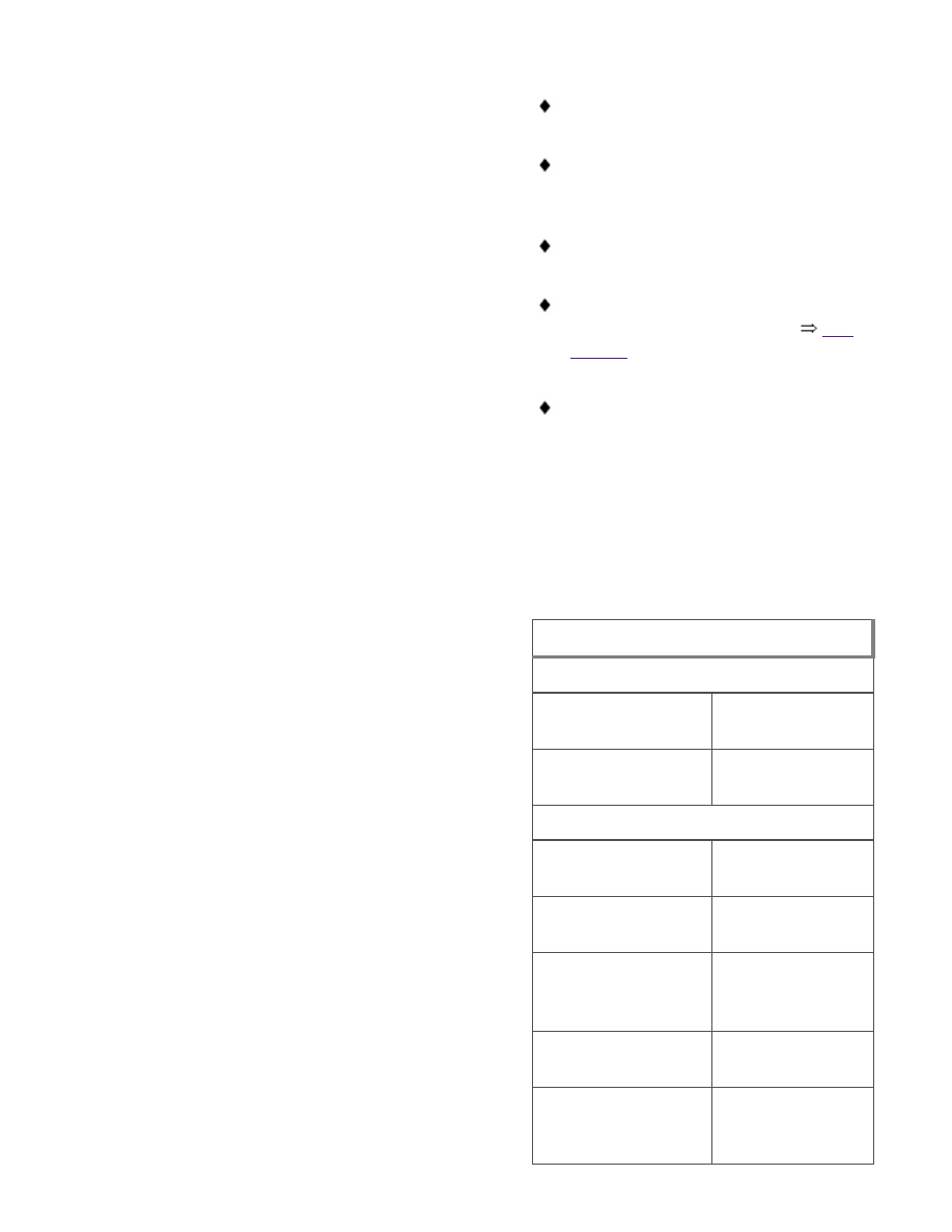
Tightening torques
Drive axle collar nut to drive flange
M24
250 Nm (184
ft-lb)
M27
300 Nm (221
ft-lb)
Drive axle to final drive flange
M10x20 mm Torx
bolt
83 Nm (61 ft-lb)
M10x46 mm bolt
(black)
100 Nm (74 ft-lb)
M10x46 mm bolt
(silver) (always
replace)
80 Nm (59 ft-lb)
Road wheel to hub
100 ± 10 Nm
(74 ± 7 ft-lb)
Shock absorber to
trailing arm (car in
100 Nm (74 ft-lb)
Tightening torques
normal loaded
position)
Trailing arm bracket
to body (M12 bolt)
77 Nm (57 ft-lb)
Trailing arm to
upper or lower
control arm (M12
bolt)
110 Nm (81 ft-lb)
Upper control arm, removing
and installing
-
Remove drive axle as described in
331 Rear Axle Final Drive
.
WARNING!
Make sure that the car is firmly
supported on jack stands designed for
the purpose. Place the jack stands
beneath a structural chassis point. Do
not place jack stands under
suspension parts.
-
Remove coil spring as described
earlier.
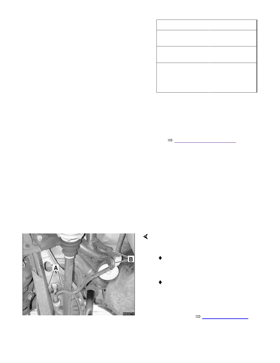
Remove stabilizer bar link bolts (A) at
upper control arm.
Remove stabilizer bar anchor bolts
(B).
Carefully push stabilizer bar aside.
Note:
Do not twist stabilizer bar link bushing on
end of bar. See
Rear Stabilizer Bar
later in this repair group.

-
If necessary, remove ride level
sensor from upper control arm.
-
Unbolt upper control arm from both
trailing arm and rear subframe.
Note direction of bolt insertion.
Note:
For clearance reasons, it may be
necessary to unbolt the differential from
the subframe and push it toward the rear
of the car in order to remove the control
arm mounting bolt from the subframe.
-
Installation is reverse of removal,
noting the following;
Insert mounting bolts in direction
previously marked
Always use new self-locking nuts.
Have car professionally aligned
when job is complete.
Tightening torques
Drive axle collar nut to drive flange
M24
250 Nm (184
ft-lb)
M27
300 Nm (221
ft-lb)
Drive axle to final drive flange
M10x20 mm Torx
bolt
83 Nm (61 ft-lb)
M10x46 mm bolt
(black)
100 Nm (74 ft-lb)
M10x46 mm bolt
(silver) (always
replace)
80 Nm (59 ft-lb)
Tightening torques
Road wheel to hub
100 ± 10 Nm
(74 ± 7 ft-lb)
Shock absorber to
trailing arm car in
normal loaded
position
100 Nm (74 ft-lb)
Upper control arm
to rear subframe
M12 bolt
77 Nm (57 ft-lb)
Upper control arm
to trailing arm M12
bolt
110 Nm (81 ft-lb)
Lower control arm, removing
and installing
-
Raise rear end of car and support it
securely on jackstands. Remove
rear wheel.
-
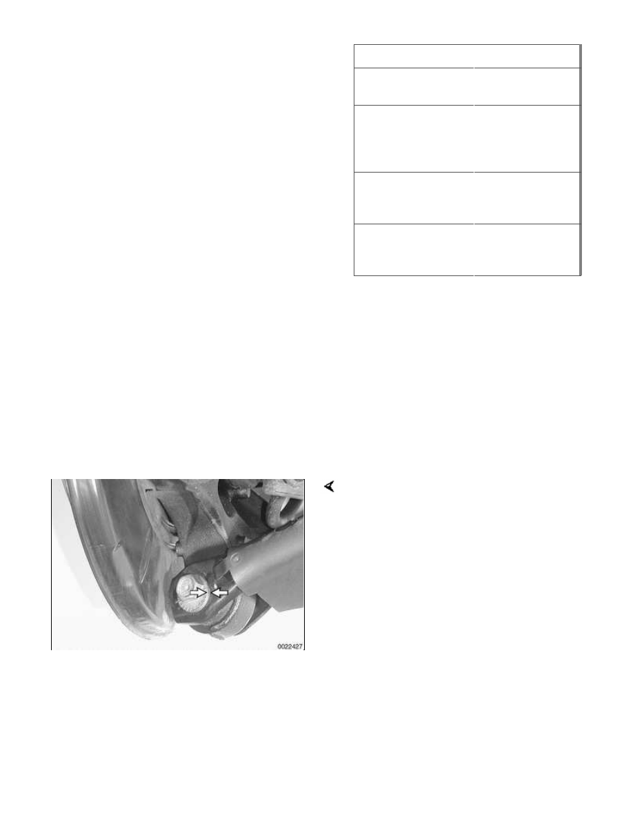
Support trailing arm from below
using an adjustable jackstand.
Mark position (arrows) of lower control
arm eccentric mounting bolt.
-
Remove lower control arm plastic
shield.
-
Remove both lower control arm
mounting bolts. Note direction of
bolt insertion.
Note:
For clearance reasons, it may be
necessary to unbolt the differential from
the subframe and push it toward the rear
of the car in order to remove the control
arm mounting bolt from the subframe.
Нет комментариевНе стесняйтесь поделиться с нами вашим ценным мнением.
Текст