BMW 3 (E46). Manual — part 163
Rear subframe bushing
-
Remove subframe as described
earlier.
-
In case of damage to subframe
mounting stud threads, replace
stud.
-
In case of damage to subframe
mounting stud threads in body,
repair using Helicoil thread insert
M12 x 1.5 x18.
-
Press old bushing out and install
new bushing using appropriate
press tools. Coat new bushing with
Circolight® or equivalent rubber
bonding agent.
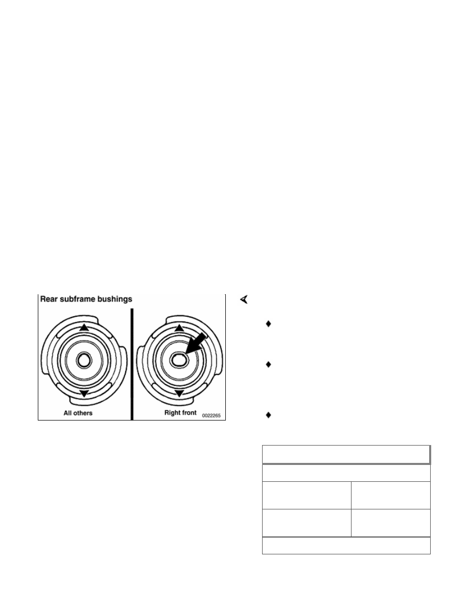
Bushing position and orientation:
Right front bushing has elongated
hole (arrow).
Orient all bushings with triangular
arrow heads pointing front/aft on
car.
Have car professionally aligned
when job is complete.
Tightening torque
Drive axle collar nut to drive flange
M24
250 Nm (184
ft-lb)
M27
300 Nm (221
ft-lb)
Drive axle to final drive flange

Tightening torque
M10x20 mm Torx
bolt
83 Nm (61 ft-lb)
M10x46 mm bolt
(black)
100 Nm (74 ft-lb)
M10x46 mm bolt
(silver) (always
replace)
80 Nm (59 ft-lb)
Road wheel to hub
100 ± 10 Nm
(74 ± 7 ft-lb)
Shock absorber to
trailing arm (car in
normal loaded
position)
100 Nm (74 ft-lb)
Subframe to body
(M12)
77 Nm (57 ft-lb)
Upper control arm
to rear subframe
M12 bolt
77 Nm (57 ft-lb)
Upper control arm
to trailing arm M12
bolt
110 Nm (81 ft-lb)

330-4
Rear Stabilizer Bar
The rear stabilizer bar is mounted to
the rear subframe and attached via
stabilizer bar links to the rear upper
control arms.
1 - Stabilizer bar
2 - Self-locking nut M8
3 - Rubber mounting
4 - Clamping support
5 - Bolt M8
6 - Bolt M
7 - Stabilizer link support bracket
8 - Bolt M8
9 - Self-locking nut
10 - M8 Self-locking nut
11 - M8 Stabilizer link
When installing new stabilizer link:
Clean rubber seating surface at
end of stabilizer bar.
Moisten end of bar and inside
rubber mount (in link end). with
Circolight® or equivalent rubber
bonding agent.
Push bar into rubber mount and
position as shown in illustration.
Once rubber bond has set
stabilizer link can no longer be
rotated

330-5
Rear Wheel Bearings
The rear wheel bearing is a unitized
assembly and is not repairable
separately.
Special press tools, to be used with the
trailing arm attached to the car, are
required to replace a wheel bearing.
Read the procedure through before
beginning the job.
Rear wheel bearing, replacing
-
Remove drive axle as described in
331 Rear Axle Final Drive
.
WARNING!
Make sure that the car is firmly
supported on jack stands designed
for the purpose. Place the jack
stands beneath a structural chassis
point. Do not place jack stands
under suspension parts.
-
Right side: Detach brake pad
sensor connector at brake caliper.
-
Remove brake caliper assembly
and rotor as described in
340
Brakes
. Leave brake hose
connected to caliper. Suspend
caliper assembly from chassis
using stiff wire.
Remove ABS pulse sensor at trailing
arm.
Нет комментариевНе стесняйтесь поделиться с нами вашим ценным мнением.
Текст