Hummer H1 (1992-1998). Manual — part 53
2-41. ENGINE ASSEMBLY FROM SUBASSEMBLIES (Cont’d)
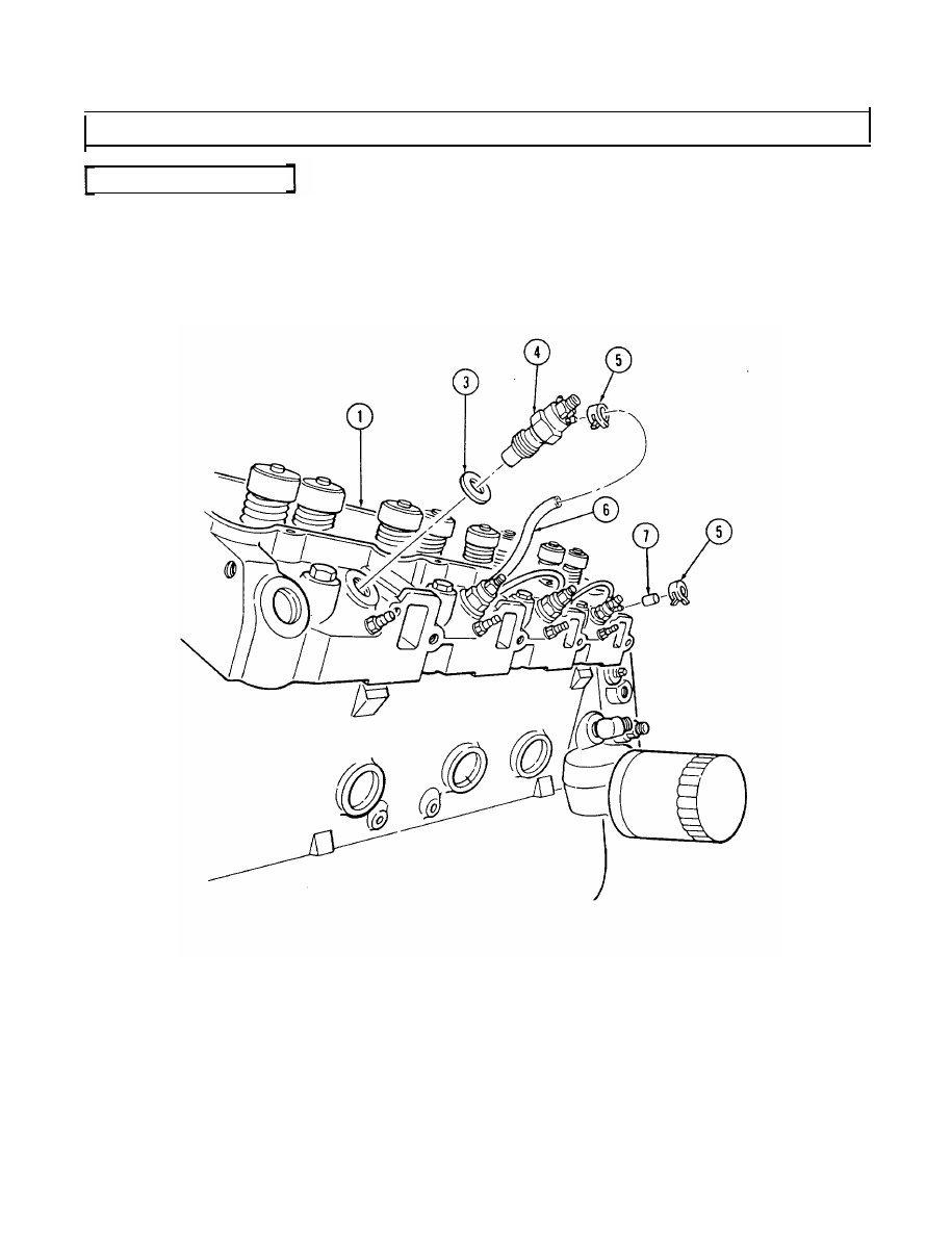
q. Fuel Injection Nozzles
1. Install four gaskets (3) and fuel injection nozzles (4) into cylinder head (1). Using injector nozzle
socket, tighten fuel injection nozzles (4) to 44-60 lb-ft (60-81 N•m).
2. Install three hoses (6) on fuel injection nozzles (4) with six clamps (5).
3. Install cap (7) on rear fuel injection nozzle (4) with clamp (5).
4. Repeat steps 1 through 3 for opposite side.
2-175

2-41. ENGINE ASSEMBLY FROM SUBASSEMBLIES (Cont’d)
r. Rocker Arm Shaft and Pushrods
CAUTION
Marked ends of pushrods must point up when installed or engine
damage may result.
1. Install eight pushrods (1) in proper location with marked end of pushrods (1) up. Make sure
pushrods (1) are properly seated.
2. Install two rocker arm and shaft assemblies (2) on cylinder head (6). Make sure pushrods (1)
properly seat in rocker arms (3).
3. Secure rocker arm and shaft assemblies (2) with four retainers (4) and capscrews (5). Tighten
capscrews (5) to 41 lb-ft (56 N•m).
4. Repeat steps 1 through 3 for opposite side.
2-176
2-41. ENGINE ASSEMBLY FROM SUBASSEMBLIES (Cont’d)
s. Rocker Arm Covers
NOTE
●
If applying sealant, perform step 2. Keep sealant out of capscrew holes.
●
If installing new rocker arm cover gaskets, perform step 1, then step 3.
●
Silicone sealant can be used with the gasket, but is not required.
1. Install rocker arm cover gasket (13) on lip of cover (12) and align with capscrew holes.
2. Apply a 1/16-in. (4 mm) bead of silicone sealant around sealing surface of rocker arm covers (11).
3. Install rocker arm covers (11) on cylinder head (6) with sixteen washers (10), seven capscrews (9),
and nine studs (14), following assembly diagram.
4. Tighten capscrews (9) and studs (14) to 13-25 lb-ft (18-34 N•m).
5. Install two injection line support brackets (8) on studs (12) with four nuts (7). Tighten nuts (7) to
13-20 lb-ft (18-27 N•m).
RIGHT ROCKER ARM COVER
LEFT ROCKER ARM COVER
2-177
2-41. ENGINE ASSEMBLY FROM SUBASSEMBLIES (Cont’d)
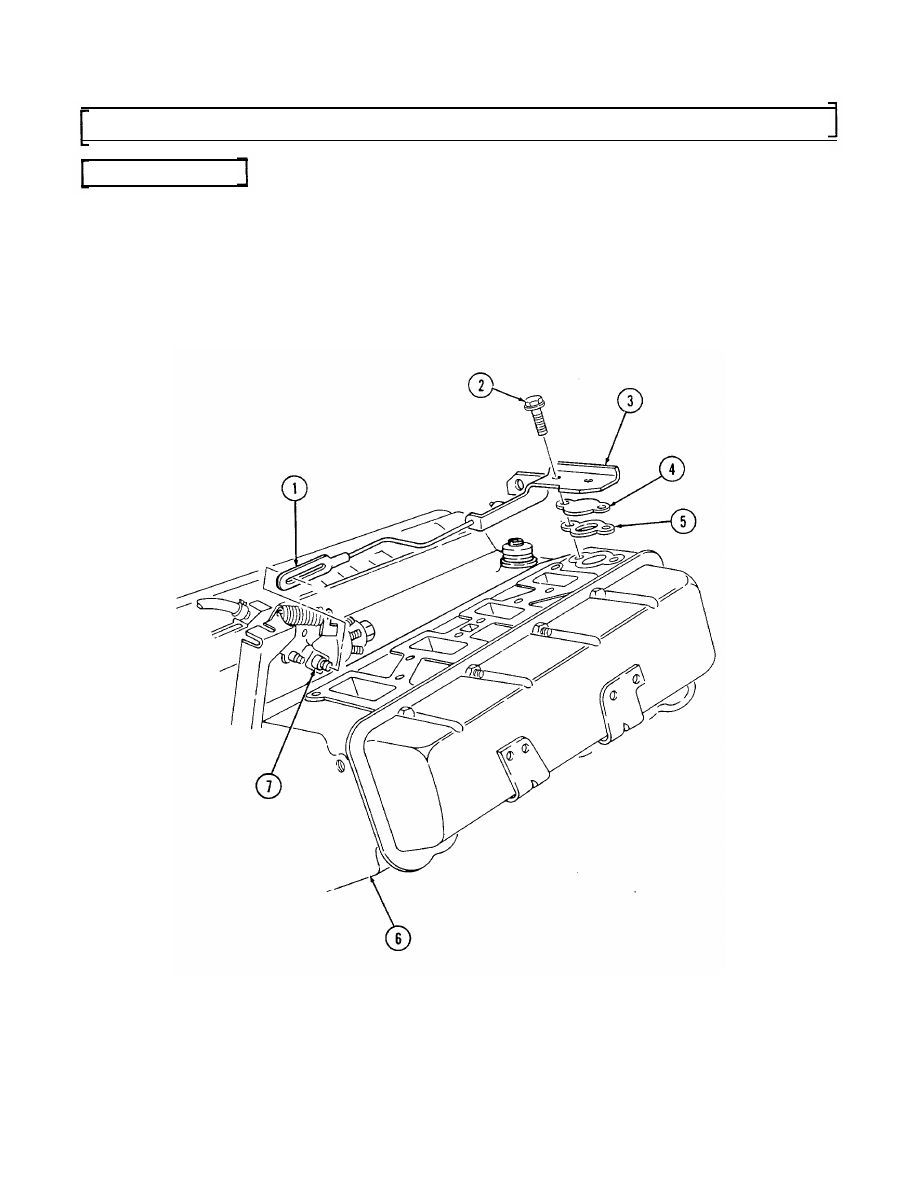
t. Modulator Link
NOTE
Installation of the modulator link is applicable only to 6.2L
engines.
1. Attach modulator link (1) to throttle lever (7).
2. Install water jacket cover gasket (5), water jacket cover (4), and modulator link bracket (3) on
cylinder head (6) and secure fith capscrews (2).
3. Tighten capscrews (2) to 25-37 lb-ft (3450 N•m).
2-178
Нет комментариевНе стесняйтесь поделиться с нами вашим ценным мнением.
Текст