Hummer H1 (1992-1998). Manual — part 52
2-41. ENGINE ASSEMBLY FROM SUBASSEMBLIES (Cont’d)
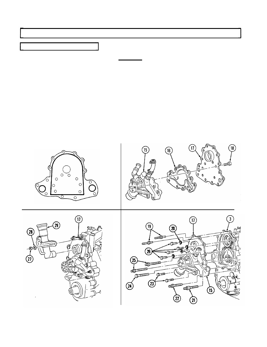
m. Water Pump and Adapter Plate
1.
2.
3.
4.
5.
6.
CAUTION
Ensure water pump P/N 23500085 is used on 6.5 L engines or
damage to equipment will result.
Install gasket (16) and water pump (15) on adapter plate (17) with seven capscrews (18). Tighten
capscrews (18) to 13-20 lb-ft (18-27 N•m).
Apply sealer to sealing surfaces on adapter plate (17), following diagram shown.
Apply pipe sealing compound to capscrews (24) and (23).
Install adapter plate (17) and water pump (15) on timing gear cover (3) with two long studs (25),
short stud with thick hex (21), stud (22), and capscrew (24).
Install two long capscrews (23), studs (19), four washers (20), and capscrews (26). Tighten studs (19)
and capscrews (26) and (23) to 13-20 lb-ft (18-27 N•m). Tighten studs (21), (22), and (25), and
capscrew (24) to 24-37 lb-ft (34-50 N•m).
Install oil fill tube (29) on adapter plate (17) with two washers (28) and nuts (27). Tighten nuts (27)
to 13-20 lb-ft (18-27 N•m).
SEALER DIAGRAM
2-171
2-41. ENGINE ASSEMBLY FROM SUBASSEMBLIES (Cont’d)
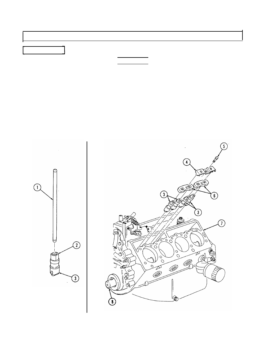
n. Valve Lifters
WARNING
1.
2.
3.
4.
5.
6.
7.
Diesel fuel is highly flammable. Do not perform this procedure
near fire, flame, or sparks. Severe injury or death may result.
Submerge eight lifters (3) in clean diesel fuel or kerosene and work plunger (2) up and down with
pushrod (1) to prime lifters (3).
Apply OE/HDO to lifters (3).
Install lifters (3) into cylinder block (7).
Install four guide plates (6) on lifters (3).
Install two guide plate clamps (4) with two capscrews (5). Tighten capscrews (5) to 15-20 lb-ft
(20-27 N•m).
Repeat steps 1 through 5 for opposite side.
Manually rotate crankshaft (8) two complete revolutions to ensure free movement of lifters (3).
2-172
Change 2 2-173
2-41. ENGINE ASSEMBLY FROM SUBASSEMBLIES (Cont’d)
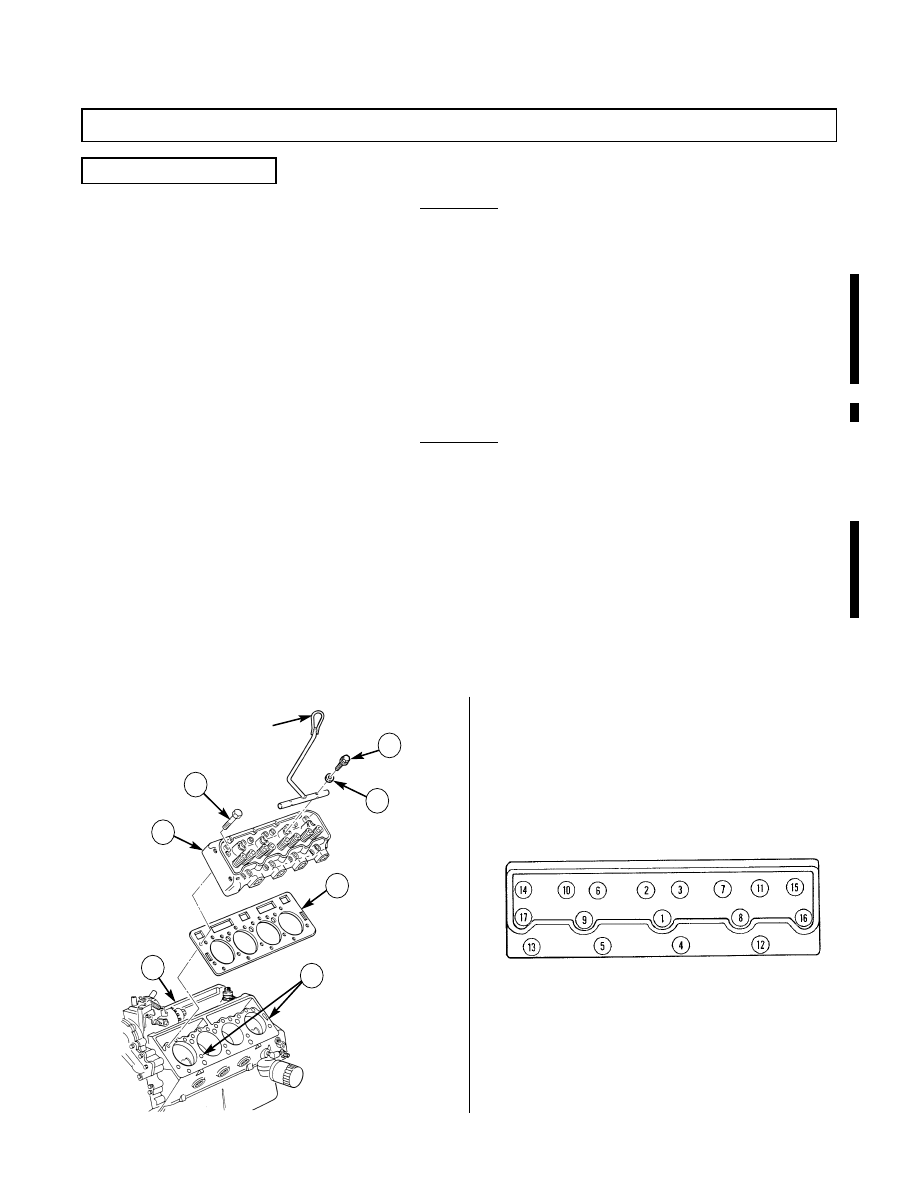
o. Cylinder Heads
C
CA
AU
UT
TIIO
ON
N
Head gasket must be used without sealer. Additional sealant may
cause leaks or damage to engine.
1.
Install head gasket (11) over dowel pins (12) on cylinder block (7).
N
NO
OT
TE
E
Use of cylinder head lifting device is optional.
1.1. Install cylinder head lifting device on center of cylinder head (9) with two washers (10.2) and
capscrews (10.1).
1.2. Install cylinder head (9) on cylinder block (7) and remove two capscrews (10.1), washers (10.2), and
cylinder head lifting device.
2.
Clean threads of capscrews (10) with a wire brush to remove old pipe sealing compound. Apply pipe
sealing compound to threads and under heads of capscrews (10).
C
CA
AU
UT
TIIO
ON
N
Failure to tighten cylinder head capscrews in proper sequence
may result in leaks or damage to cylinder head.
3.
Install cylinder head (9) on cylinder block (7) with seventeen capscrews (10). Tighten capscrews (10)
to 20 lb-ft (27 N
•
m), following torque sequence shown.
4.
For 6.2 L engine, tighten seventeen capscrews (10) to 50 lb-ft (68 N
•
m), following torque sequence
shown.
4.1 For 6.5 L engine, tighten seventeen capscrews (10) to 55 lb-ft (75 N
•
m), following torque sequence
shown.
4.2 For 6.5 L engine, retighten seventeen capscrews (10) to 55 lb-ft (75 N
•
m), following torque sequence
shown.
5.
Tighten seventeen capscrews (10) an additional 90°, following torque sequence shown and mark
capscrews (10).
6.
Repeat steps 1 through 5 for opposite side.
TORQUE SEQUENCE
10
10.1
10.2
11
9
7
12
CYLINDER HEAD
LIFTING DEVICE

2-41. ENGINE ASSEMBLY FROM SUBASSEMBLIES (Cont’d)
1. Install four glow plugs (2) into cylinder head (l). Using glow plug socket, tighten glow plugs (2)
to 8-12 lb-ft (11-16 N•m).
2. Repeat step 1 for opposite side.
2-174
Нет комментариевНе стесняйтесь поделиться с нами вашим ценным мнением.
Текст