Hummer H1 (2002+). Manual — part 93

___________________________________________
Transmission/Transfer Case 5-171
®
05745159
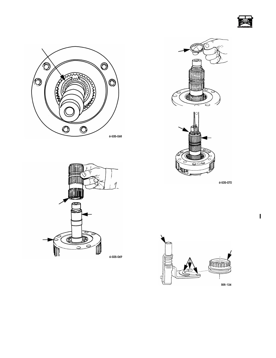
Figure 5-133: Shift Sector Installation
Figure 5-134: Input Gear/Low range Planetary
Installation
8.
Assemble differential as follows:
a.
Lubricate differential cases, gears, thrust washers
with Dexron III.
b.
Install mainshaft gear in front case.
c.
Install sprocket gear.
d.
Install thrust washer on each front case pinion pin.
e.
Install long and short pinions in sets as shown.
f.
Install thrust washer at top of each pinion.
g.
Align and install rear case on front case. Be sure case
alignment paint or scribe marks are matched as
shown.
h.
Install and tighten differential case bolts evenly.
Figure 5-135: Input Gear Snap Ring Installation
Figure 5-136: Front Retainer Seal Installation
FRONT
CASE
SHIFT
SECTOR
INPUT GEAR
BEARING
INPUT GEAR/
PLANETARY
ASSEMBLY
INPUT
GEAR
SHAFT
INPUT GEAR
BEARING
SNAP RING
FRONT
RETAINER
TOOL
J–33831

5-172
Transmission/Transfer Case
___________________________________________
®
Figure 5-137: Front Retainer Installation
Figure 5-138: Assembling Low Range Fork and Hub
Figure 5-139: Engaging Low Range Fork Pin
in Shift Sector
9.
Check condition of tone wheel on mainshaft. Replace
wheel if teeth are chipped, cracked, or broken.
10. Coat needle bearing surface of mainshaft with petroleum
jelly. Then install first spacer, 53 needle bearings, and
remaining spacer. Use extra petroleum jelly to hold needle
bearings in place (Figure 5-143).
11. Install differential on mainshaft. Verify that needle roller
bearings were not displaced before proceeding
(Figure 5-144).
12. Install differential snap ring (Figure 5-145).
13. Install intermediate clutch shaft. Be sure shaft is fully
seated (Figure 5-146).
14. Install clutch shaft thrust ring and snap ring (Figure 5-147).
Figure 5-140: Installing Mainshaft Gear In Front
Case
INPUT
GEAR
FRONT
RETAINER
HUB
PADS
LOW
RANGE
FORK
LOWER
SLOT
SHIFT
SECTOR
LOW
RANGE
FORK
MAINSHAFT
GEAR
DIFFERENTIAL
FRONT CASE

___________________________________________
Transmission/Transfer Case 5-173
®
05745159
Figure 5-141: Differential Pinion and Sprocket Gear
Installation
Figure 5-142: Assembling Differential Front/Rear
Cases
Figure 5-143: Mainshaft Bearing Roller Installation
Figure 5-144: Installing Differential On Mainshaft
15. Install mode sleeve in mode fork. Replace fork pads if
worn or cracked. Do not reuse worn pads (Figure 5-148).
16. Install assembled mode fork and sleeve on mainshaft.
Then seat sleeve in differential (Figure 5-149).
17. Install assembled mainshaft, differential, mode fork, and
sleeve. Be sure mainshaft is seated in input gear pilot
bearing and that mode fork pin is seated in upper slot of
shift sector as shown (Figure 5-152).
THRUST
WASHERS (6)
SHORT
PINION (3)
THRUST
WASHERS (6)
SPROCKET
GEAR
MAINSHAFT
GEAR
FRONT
CASE
LONG
PINION (3)
CASE
ALIGNMENT
MARKS
FRONT
CASE
REAR
CASE
BEARING
SPACERS
NEEDLE ROLLER
BEARINGS
(HOLD IN PLACE
WITH PETROLEUM
JELLY)
DIFFERENTIAL
MAINSHAFT
5-174
Transmission/Transfer Case
___________________________________________
®
Figure 5-145: Differential Snap Ring Installation
Figure 5-146: Intermediate Clutch Shaft Installation
Figure 5-147: Intermediate Clutch Shaft Thrust Ring
and Snap Ring Installation
18. Install shift rail. Install rail through mode fork, range fork,
and into case bore and install lock pin (Figure 5-153).
Figure 5-148: Installing Mode Sleeve in Mode Fork
DIFFERENTIAL
SNAP RING
DIFFERENTIAL
MAINSHAFT
INTERMEDIATE
CLUTCH SHAFT
CLUTCH SHAFT
THRUST RING
INTERMEDIATE
CLUTCH SHAFT
CLUTCH SHAFT
SNAP RING
MODE FORK
ASSEMBLY
FORK
PADS
MODE
SLEEVE
4-1-00
Нет комментариевНе стесняйтесь поделиться с нами вашим ценным мнением.
Текст