Hummer H1 (2002+). Manual — part 91

___________________________________________
Transmission/Transfer Case 5-163
®
05745159
Figure 5-105: Sector Shaft Bushing and O-Ring
Removal
29. Remove bolts attaching front retainer to front case. Then
remove retainer by prying it loose with screwdriver
positioned in retainer slot (Figure 5-106).
Figure 5-106: Front Retainer Removal
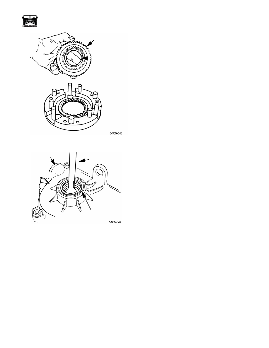
30. Remove snap ring that secures input gear in bearing
(Figure 5-107).
31. Remove input gear and low range planetary as assembly.
Tap input gear with rawhide or plastic mallet to free it
from bearing.
32. Disassemble input gear and low range planetary as
follows:
a.
Remove retaining ring that secures input gear in low
range planetary (Figure 5-108).
b.
Remove lock ring and front thrust washer (Figure 5-109).
c.
Remove input gear and rear thrust washer from low
range planetary (Figure 5-109).
Figure 5-107: Input Gear Snap Ring Removal
Figure 5-108: Input Gear Retaining Ring Removal
SHAFT
SECTOR
BUSHING
O-RING
FRONT
RETAINER
RETAINER
SLOT
SNAP RING
INPUT GEAR
INPUT GEAR
LOW RANGE
PLANETARY
RETAINING
RING

5-164
Transmission/Transfer Case
___________________________________________
®
Figure 5-109: Input/Low Range Planetary Gear
Disassembly Sequence
33. Remove and disassemble differential as follows:
a.
Scribe or paint mark front and rear cases for assembly
reference (Figure 5-110).
b.
Remove case bolts (Figure 5-111).
c.
Pry front and rear cases apart with two screwdrivers
(Figure 5-112).
d.
Remove planet gears and thrust washers (Figure 5-113).
e.
Remove sprocket and mainshaft gears as assembly
(Figure 5-114).
34. Remove front output shaft front bearing seal with pry tool
(Figure 5-115).
Figure 5-110: Marking Differential Cases for
Assembly Reference
Figure 5-111: Differential Case Bolt Removal
Figure 5-112: Separating Differential Cases
Figure 5-113: Planet Gear Locations In Bottom Case
LOW RANGE
PLANETARY
INPUT
GEAR
LOCK RING
FRONT
THRUST
WASHER
REAR
THRUST
WASHER
REAR CASE
FRONT CASE
ALIGNMENT SCRIBE
OR PAINT MARK
CASE BOLTS
FRONT CASE
REAR CASE
SPROCKET
GEAR
PLANET
GEARS (6)
FRONT
CASE
THRUST
WASHERS (12)
___________________________________________
Transmission/Transfer Case 5-165
®
05745159
Figure 5-114: Mainshaft and Sprocket Gear
Removal
Figure 5-115: Removing Front Output Shaft Seal
TRANSFER CASE CLEANING AND
INSPECTION
Clean the transfer case components thoroughly with standard
parts cleaning solvent. Remove all traces of sealer from the
case and retainer sealing surfaces.
Clean the oil pickup screen with solvent and dry it with com-
pressed air. Also use compressed air to remove solvent residue
from all oil feed passages and channels.
Geartrain
The differential pinion gears and thrust washers are serviceable
components and can be replaced if worn or damaged. The dif-
ferential cases are also serviceable but must be replaced as a set
if either case is damaged.
Inspect the mainshaft splines, gear teeth and bearing surfaces
carefully for evidence of wear, or damage. Replace the shaft if
necessary. Do not attempt to salvage it if damaged.
The range and mode forks are serviced as assemblies. Replace
either part if damaged. However, the nylon pads in the forks
can be replaced if worn, or cracked.
Inspect the transfer case snap rings closely. Do not attempt to
salvage a distorted snap ring by straightening or reshaping it.
Replace any snap ring that is distorted, or worn.
Inspect the low range planetary, input gear and thrust washer,
retainer, and snap ring. The low range planetary is serviced as
an assembly only. Replace it if the case or pinions are dam-
aged.
During inspection, also make sure the seal surface of the input
gear is in good condition. Minor nicks on this surface can be
reduced with crocus cloth. However, replace the gear if the seal
surface is severely scored or worn.
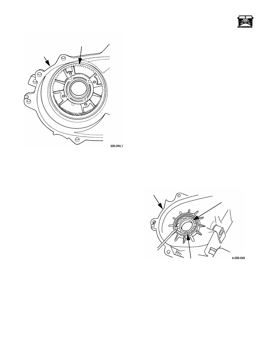
Check condition of the low range annulus gear (Figure 5-116).
Replace the front case and gear as an assembly if the gear is
damaged. The annulus gear is not serviced separately.
The speedometer tone wheel should be replaced if worn,
cracked, or spline teeth are worn.
Inspect the differential gears, thrust washers and case halves.
Replace the mainshaft gear if the gear teeth or the brass ring on
the underside of the gear are damaged. Replace the differential
as an assembly if the gears, case halves, or the pins in the lower
case half are damaged.
Inspect the case halves, extension housing, and both retainers
for cracks, porosity, or damaged sealing surfaces. Inspect the
shafts, gears, chain and shift components for wear or damage.
Inspect all of the transfer case bearings for wear, roughness,
pitting, or galling. Replace worn or damaged bearings.
MAINSHAFT GEAR
SPROCKET GEAR
SHAFT
SEAL
FRONT CASE
PRY TOOL
5-166
Transmission/Transfer Case
___________________________________________
®
Figure 5-116: Annulus Gear Location In Front Case
Oil Pump
The oil pump is not a serviceable component. Replace the
pump as an assembly if the gear teeth are worn, or if the pump
has become damaged.
Bearings and Seals
The transfer case seals should be replaced during overhaul.
Use new seals in the oil pump, input gear bearing retainer,
front case, and extension housing. Also replace the yoke seal
washer and detent plug O-ring.
FRONT OUTPUT SHAFT BEARING AND SEAL
REPLACEMENT
1.
Remove snap ring securing shaft front bearing in front
case (Figure 5-117).
2.
Tap old bearing out rear of front case with plastic or raw
hide mallet.
3.
Install new bearing with tool handle J–8092 and installer
tool J–33833 (Figure 5-118).
4.
Lubricate new bearing with Dexron III.
5.
Install new shaft seal with seal installer J–38869
(Figure 5-119). Then lubricate seal lip with Dexron III.
6.
Remove front output shaft rear bearing from rear case as
follows:
a.
Clamp rear case to bench with wood blocks and C-
clamps.
b.
Pull bearing using slide hammer, adapter J–2619-01,
and puller J–26369 (Figure 5-120).
c.
Install new bearing with tool handle J–8092 and
installer J–33832 (Figure 5-121). The rear bearing
bore is chamfered at the top. Install the bearing so it is
flush with the chamfer lower edge.
CAUTION: Do not bottom the bearing in the bore. This will
block the oil feed hole in the rear case bearing bore.
Figure 5-117: Front Output Shaft Front Bearing Snap
Ring Removal/Installation
FRONT CASE
ANNULUS GEAR
FRONT CASE
BEARING
SNAP RING
FRONT OUTPUT
SHAFT FRONT
BEARING
Нет комментариевНе стесняйтесь поделиться с нами вашим ценным мнением.
Текст