Hummer H1 (2002+). Manual — part 126
_________________________________________________________
Steering System 8-11
®
05745159
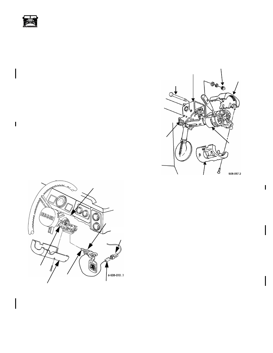
IGNITION SWITCH LOCK CYLINDER
REPLACEMENT
Removal
1.
Disconnect battery ground cable.
2.
Remove close-out panel.
3.
Remove five screws and lower steering column shroud
(Figure 8-16).
4.
Disconnect lock cylinder connector from ignition switch
connector.
5.
Turn ignition switch to RUN position.
6.
Depress lock cylinder detent pin through detent pin hole
and remove lock cylinder from steering column.
Installation
1.
Insert lock cylinder into steering column (Figure 8-16).
2.
Turn ignition switch to LOCK position.
3.
Connect lock cylinder connector to ignition switch
connector.
4.
Secure lower steering column shroud to steering column
with five screws.
5.
Install close-out panel.
6.
Connect battery ground cable.
7.
Verify that ignition switch lock cylinder operates properly.
Figure 8-16: Ignition Switch Lock Cylinder
Replacement
IGNITION INTERLOCK CABLE REPLACEMENT
Removal
1.
Remove five screws and lower shroud from steering col-
umn (Figure 8-17).
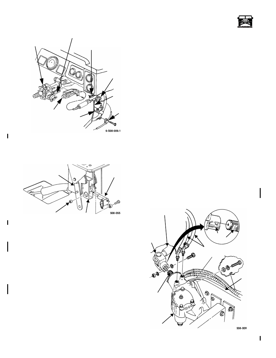
Figure 8-17: Steering Column Shrouds
2.
Loosen two locknuts securing steering column to
mounting bracket.
3.
Remove locknut, lockwasher, three washers, and bolt
securing steering column to mounting bracket.
4.
Lower steering column and remove upper shroud.
5.
Remove screw and interlock cable from ignition switch
(Figure 8-18).
6.
Disconnect connector from interlock cable.
7.
Raise and secure hood.
8.
Remove screw securing clamp and interlock cable to
bracket. Remove clamp from interlock cable.
9.
Remove close-out panel (Section 10).
10. Remove shifter (Section 5).
11. Remove nut and screw securing interlock cable to shifter
(Figure 8-19).
12. Remove interlock cable and grommet from vehicle.
STEERING COLUMN
LOCK
LOCK CYLINDER
CONNECTOR
CYLINDER
LOCK CYLINDER
DETENT PIN
LOWER STEERING
COLUMN SHROUD
DETENT
PIN HOLE
IGNITION
SWITCH
CONNECTOR
UPPER SHROUD
LOWER SHROUD
STEERING
MOUNTING BRACKET
COLUMN
10 lb-ft
31 lb-ft (42 N•m)
(14 N•m)
BOLT
4-1-00
8-12
Steering System
__________________________________________________________
®
Figure 8-18: Interlock Cable/Ignition Switch
Installation
1.
Secure interlock cable to shifter with screw and nut.
Tighten nut to 8 lb-ft (11 N•m) (Figure 8-19).
Figure 8-19: Interlock Cable and Shifter
2.
Route interlock cable through bracket and install shifter
(Section 5).
3.
Secure interlock cable to bracket with clamp and screw
(Figure 8-18).
4.
Route interlock cable through cowl and secure with
grommet.
5.
Lower and secure hood.
6.
Secure interlock cable to ignition switch with screw.
7.
Connect connector to interlock cable.
8.
Position upper steering column shroud on steering column
(Figure 8-17).
9.
Raise steering column and secure steering column on
mounting bracket with bolt, three washers, lockwasher,
and locknut. Tighten locknut to 31 lb-ft. (42 N•m).
10. Tighten two locknuts securing steering column to
mounting bracket. Tighten locknuts to 10 lb-ft (14 N•m).
11. Secure lower steering column shroud to upper shroud with
five screws.
12. Install close-out panel (Section 10).
Test
1.
With transmission lever in P, turn ignition key to run.
2.
Activate brake switch and move transmission lever to N.
3.
Without turning ignition key off, move transmission shift
lever to P.
4.
Turn ignition key off. To pass test, it should not be
possible to move transmission lever out of P unless an
extremely high effort is applied.
5.
Turn ignition key on. To pass test, it should not be
possible to move transmission lever out of P unless an
extremely high effort is applied.
6.
Activate brake switch. To pass test, transmission lever
should be moved from P to N with normal shift effort.
7.
Turn ignition key off. To pass test, it should not be
possible to remove ignition key while transmission lever is
in N.
8.
Move transmission lever to P. To pass test, it must be
possible to remove ignition key with normal effort applied
to ignition key.
STEERING GEAR REPLACEMENT
Removal
NOTE: Ensure front wheels are in the straight-ahead position.
Have drainage container ready to catch fluid.
1.
Disconnect two power steering lines from steering gear
(Figure 8-20).
Figure 8-20: Steering Gear Mounting
LOCK AND SWITCH
CONNECTOR
GROMMET
CLAMP
BRACKET
INTERLOCK CABLE
COWL
HOUSING ASSEMBLY
IGNITION SWITCH
SHIFTER
INTERLOCK
CABLE
BRACKET
8 lb-ft (11 N•m)
INTERMEDIATE SHAFT
YOKE
STEERING
STEERING
POWER STEERING LINES
FRAME
YOKE
NOTCH
SPLINES
GEAR
GEAR
4-1-00
_________________________________________________________
Steering System 8-13
®
05745159
2.
Turn steering wheel left and right several times to bleed
off power steering fluid.
3.
Remove bolt on intermediate shaft yoke at steering gear
and disconnect intermediate shaft from steering gear.
4.
Remove nut and lockwasher from steering arm
(Figure 8-21).
5.
Using puller J–42548, remove steering arm from shaft.
6.
Remove three bolts, lockwashers, washers, and steering
gear from frame (Figure 8-20).
Installation
1.
Align steering gear with mounting holes in frame and
secure with three washers, lockwashers, and bolts. Tighten
bolts to 54-66 lb-ft (73-89 N•m) (Figure 8-20).
2.
Align hole in yoke with notch on steering gear splines and
slide intermediate shaft on steering gear splines.
3.
Insert bolt in yoke and tighten locknut to 60 lb-ft (81
N•m).
4.
Connect two power steering lines to steering gear.
NOTE: Ensure front wheels are in the straight ahead position.
5.
Install steering arm on shaft with lockwasher and nut.
Tighten nut to 185 lb-ft (251 N•m) (Figure 8-21).
6.
Fill power steering reservoir.
7.
Purge air from power steering system (Refer to “Purging
Air From the Power Steering System” on page 8–22 ).
8.
Inspect wheel alignment.
INTERMEDIATE STEERING SHAFT
REPLACEMENT
NOTE: Ensure front wheels are in straight-ahead position
while removing and installing intermediate steering shaft.
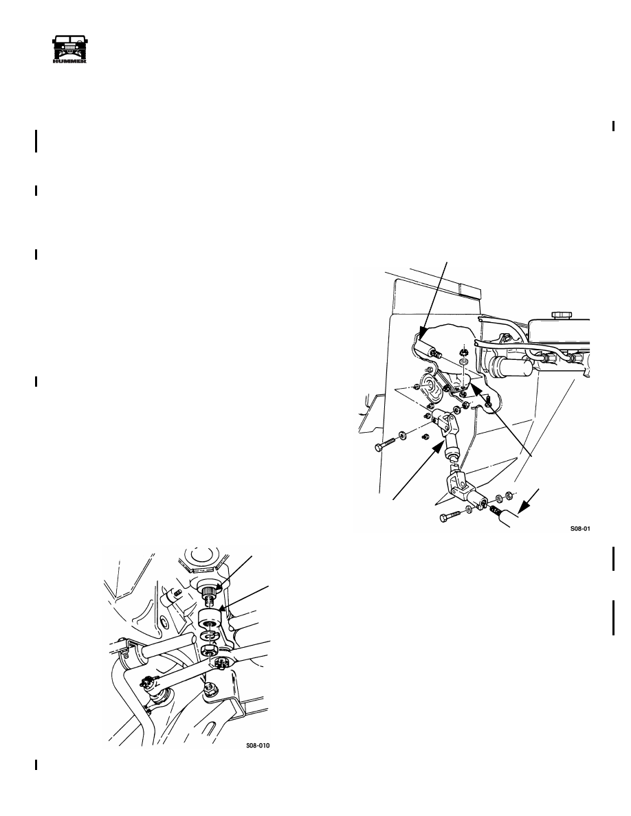
Figure 8-21: Steering Arm Removal
Removal
1.
Remove close-out panel.
2.
Remove three nuts, six washers, and three screws from
dust boot (Figure 8-22).
3.
Remove bolt on intermediate steering shaft yoke at
steering gear.
NOTE: Before performing step 4, put scribe marks showing
the position of the yoke relative to the splines.
4.
Remove bolt on intermediate steering shaft yoke at
steering column and remove shaft.
Figure 8-22: Intermediate Steering Shaft
Removal
Installation
1.
Align hole in yoke with notch on steering gear splines
(Figure 8-20). Insert bolt through yoke and tighten locknut
to 60 lb-ft (81 N•m) (Figure 8-22).
2.
Align scribe marks and slide yoke onto steering column
splines. Insert bolt through yoke and tighten locknut to 60
lb-ft (81 N•m).
3.
Apply silicone spray or equivalent to end of steering shaft.
Secure dust boot with three screws, six washers and three
nuts.
4.
Lubricate steering shaft at universal joints.
5.
Install close-out panel.
SHAFT
STEERING
ARM
STEERING COLUMN
DUST BOOT
INTERMEDIATE
STEERING SHAFT
STEERING GEAR
4-1-00
8-14
Steering System
__________________________________________________________
®
INTERMEDIATE STEERING SHAFT DUST BOOT
REPLACEMENT
Removal
1.
Remove close-out panel.
2.
Remove three nuts, six washers, and three screws from
dust boot (Figure 8-23).
NOTE: Before performing step 3, put scribe marks showing
the position of the yoke relative to the splines.
3.
Remove bolt on yoke and pull intermediate steering shaft
from steering column.
4.
Remove four locknuts, eight washers, four screws, spacer,
and dust boot from cowl panel and intermediate steering
shaft.
Installation
1.
Secure spacer and dust boot to cowl panel with four
screws, eight washers, and four locknuts. Tighten locknuts
to 60 lb-ft (81 N•m) (Figure 8-23).
2.
Insert intermediate steering shaft through dust boot. Align
scribe marks and slide yoke onto steering column splines.
Tighten locknut on yoke to 60 lb-ft (81 N•m).
3.
Apply silicone spray or equivalent to end of steering shaft.
Install three screws, six washers, and three nuts on dust
boot.
4.
Install close-out panel.
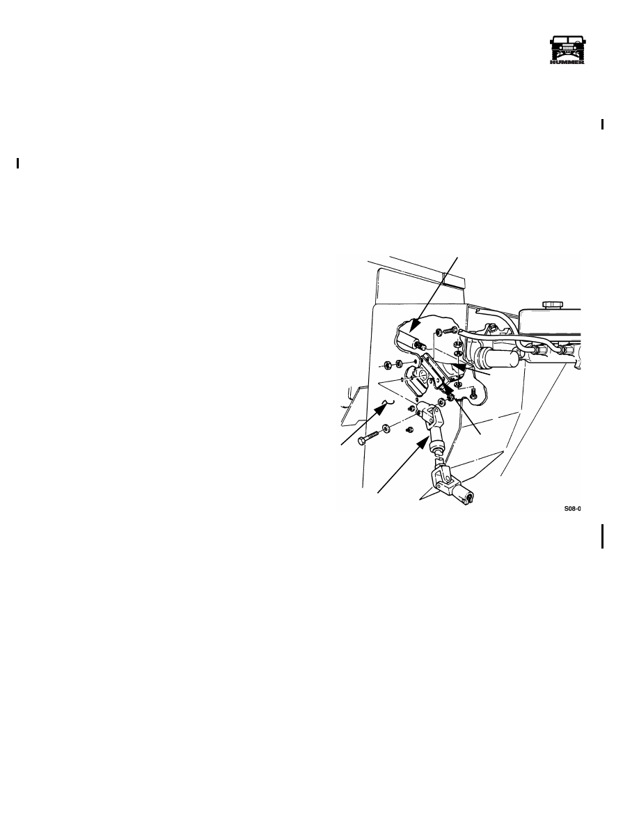
Figure 8-23: Intermediate Steering Shaft Dust Boot
Replacement
STEERING COLUMN
COWL
DUST
SPACER
INTERMEDIATE
STEERING SHAFT
BOOT
PANEL
4-1-00
Нет комментариевНе стесняйтесь поделиться с нами вашим ценным мнением.
Текст