Hummer H1 (2002+). Manual — part 127
_________________________________________________________
Steering System 8-15
®
05745159
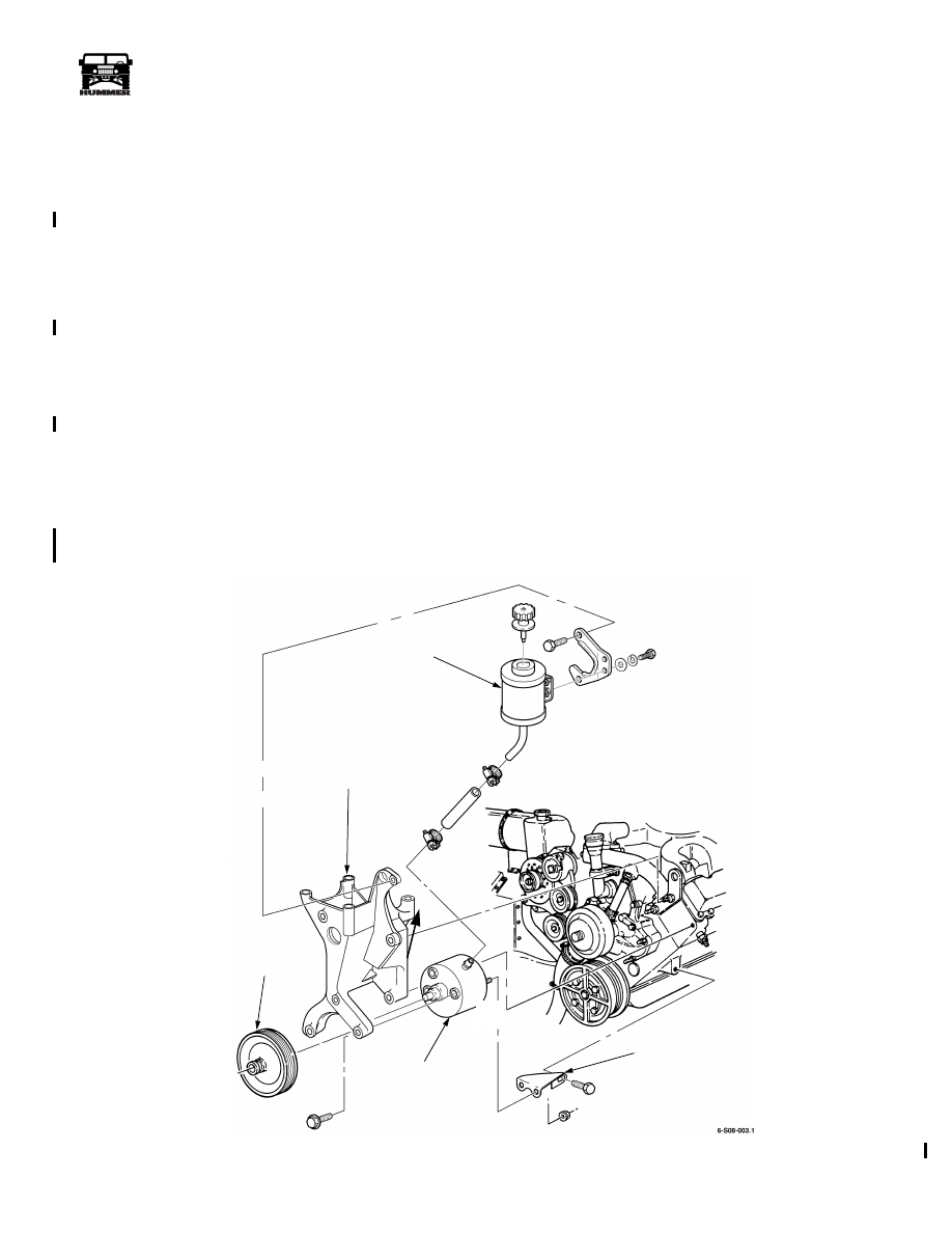
POWER STEERING PUMP AND PULLEY
REPLACEMENT
Removal
1.
Disconnect return lines and high pressure line from back
of pump (Figure 8-24).
2.
Remove serpentine belt from power steering pump pulley.
3.
Using puller J–25034-C or equivalent, remove pulley from
pump.
4.
Remove three bolts going through bracket into front of
pump (Figure 8-24).
Installation
1.
Apply non-hardening thread sealant to studs on back of
pump and secure support bracket with two nuts. Tighten
nuts to 45 lb-ft (61 N•m) (Figure 8-24)
2.
Maneuver pump into position behind power steering
bracket.
3.
Secure pump to mounting bracket with three bolts.
4.
Secure support bracket to block with bolt.
5.
Connect two return lines to power steering pump
(Figure 8-24).
6.
Check condition of O-ring seal and connect high pressure
line to back of pump.
CAUTION: In step 7, do not attempt to drive the pulley onto
the pump shaft with a hammer. The pulley and pump ring will
be damaged.
7.
Press pulley onto pump using pulley installer J–25033-C
or equivalent. Pulley should be flush +/- 0.25 mm (0.010
inch) with the end of the power steering pump shaft.
8.
Purge air from power steering system.
9.
Start engine and check for leaks.
Figure 8-24: Power Steering Pump Mounting
MOUNTING BRACKET
PULLEY
POWER STEERING
SUPPORT BRACKET
POWER
STEERING
PUMP
POWER STEERING
FLUID RESERVOIR
4-1-00
8-16
Steering System
__________________________________________________________
®
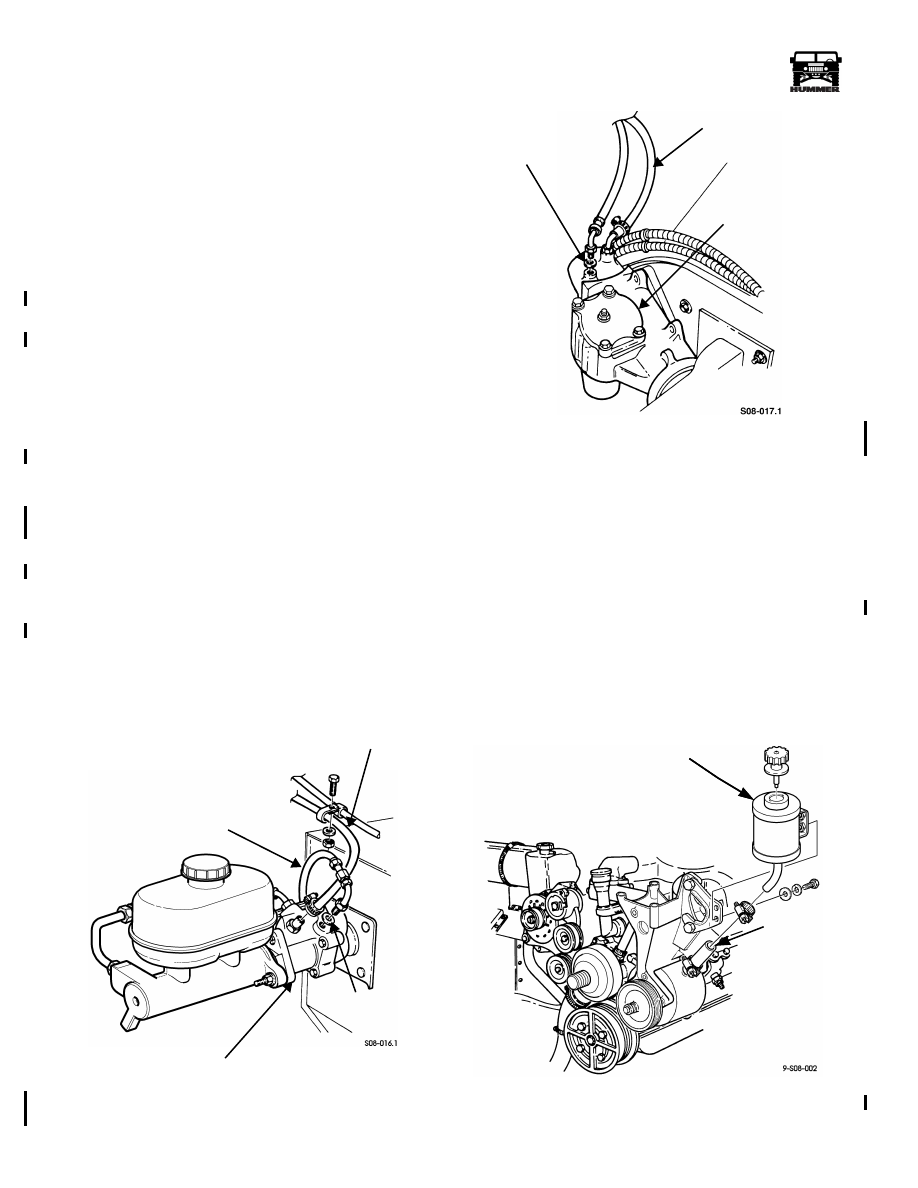
POWER STEERING HYDRAULIC SYSTEM
PRESSURE AND RETURN HOSE REPLACEMENT
NOTE: Removal and installation procedures are basically the
same for all hydraulic system pressure and return hoses. This
procedure covers the power steering pump to hydro-boost re-
turn hose and the steering gear to hydro-boost pressure hose.
Removal
1.
Disconnect return hose from power steering pump and
hydro-boost (Figures 8-25 and 8-26).
2.
Remove locknut, washer, bolt, and two clamps from
control valve hose and return hose. (Figure 8-25).
3.
Remove locknut, two washers, and bolt securing two
clamps and harness clamp to power steering line bracket.
4.
Disconnect pressure hose from hydro-boost and steering
gear and remove pressure hose. Remove two O-ring seals
from pressure hose. Check condition of O-ring seals and
replace if necessary (Figures 8-25 and 8-26).
Installation
1.
Connect pressure hose to steering gear and hydro-boost
(Figure 8-26).
2.
Connect return hose to power steering pump and hydro-
boost with two clamps (Figures 8-25 and 8-26).
3.
Install two clamps on return hose and control valve hose.
Secure return hose, control valve hose, and two clamps
together with bolt, washer, and locknut (Figure 8-25).
4.
Install harness clamp and two clamps on power steering
lines bracket with bolt, two washers, and locknut.
5.
Purge air from power steering system. Refer to (See “Purging
Air From the Power Steering System” on page 8-22) .
Figure 8-25: Power Steering Hose Replacement at
Brake Hydro-Boost
Figure 8-26: Power Steering Hose
Replacement at Steering Gear
POWER STEERING FLUID RESERVOIR REPLACE-
MENT
Removal
1.
Suction the power steering fluid from the reservoir.
2.
Loosen the hose clamp and disconnect the power steering
pump supply line from the reservoir (Figure 8-27).
3.
Remove the two bolts and washers securing the reservoir
to the bracket and remove the reservoir.
Installation
1.
Installation is the reverse of the removal procedure.
Figure 8-27: Reservoir Replacement
PRESSURE
HYDRO-BOOST
O-RING SEALS
RETURN HOSE
HOSE
PRESSURE HOSE
STEERING
O-RING SEALS
GEAR
RESERVOIR
SUPPLY LINE
4-1-00
_________________________________________________________
Steering System 8-17
®
05745159
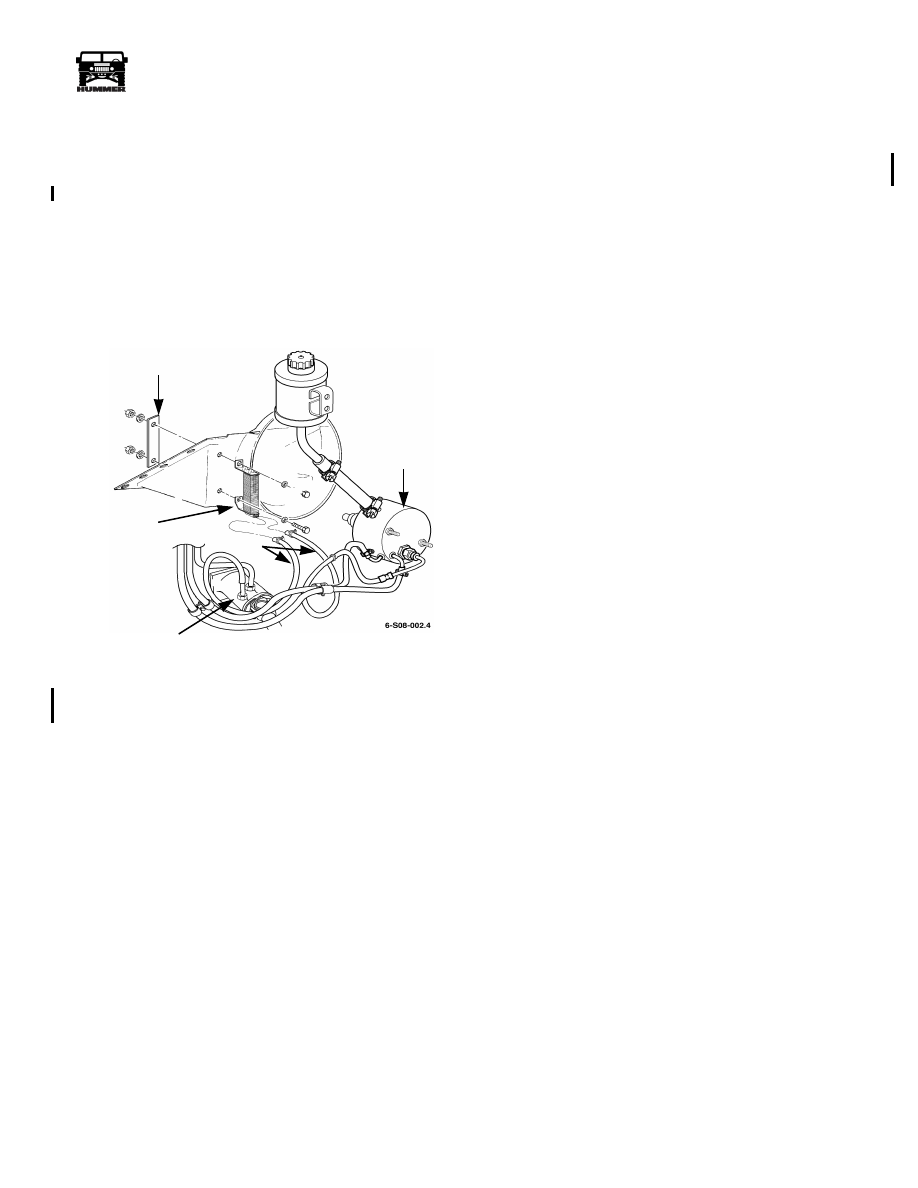
POWER STEERING COOLER AND COOLER
HOSE REPLACEMENT
Removal
1.
Disconnect two hoses from cooler (Figure 8-28).
2.
Remove cooling fan for access into fan shroud.
3.
Remove two nuts, four washers, reinforcement plate, two
bolts, and cooler.
4.
Disconnect hose at power steering gear and hose at back
of pump.
5.
Remove P-clamps holding hoses together and remove
hoses.
Figure 8-28: Power Steering Cooler and
Cooler Hoses
Installation
1.
Secure power steering oil cooler to fan shroud with two
bolts, reinforcement plate, four washers, and two nuts
(Figure 8-28).
2.
Reinstall cooling fan.
3.
Connect hoses to cooler and secure with clamps
4.
Connect other end of each hose to its respective location at
steering gear or pump and secure with clamps.
5.
Secure hoses together with P-clamps.
6.
Purge air from system.
REINFORCEMENT PLATE
POWER
STEERING
COOLER
HOSE
POWER
STEERING
GEAR
POWER
STEERING
PUMP
4-1-00
8-18
Steering System
__________________________________________________________
®
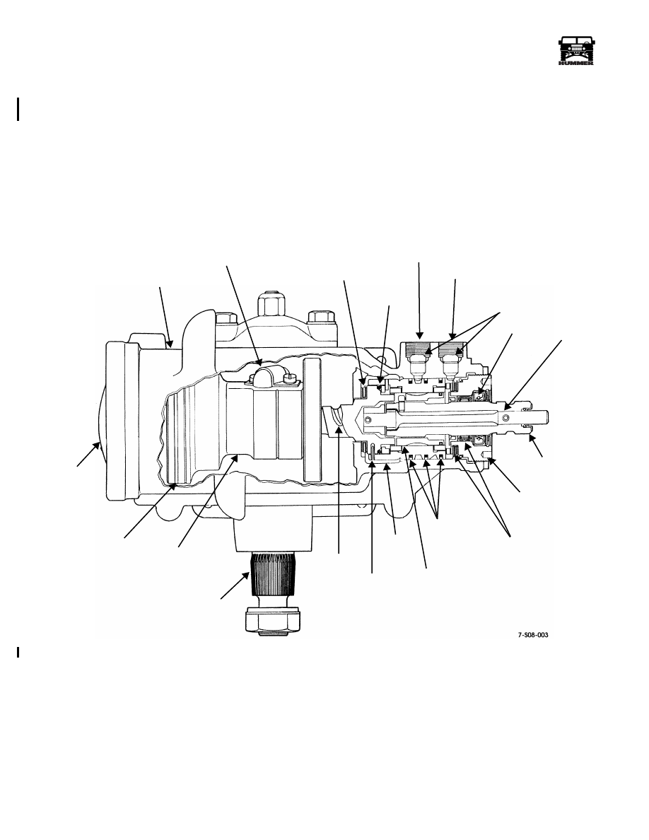
POWER STEERING GEAR SERVICE
The Saginaw recirculating ball, power steering gear
(Figure 8-29), is a fully serviceable component. The gear can
be adjusted, or overhauled as needed. Overhaul requires that
the gear be removed from the vehicle as repair can only be per-
formed on the bench.
The steering gear adjustments described in the overhaul section
can be performed on the bench or in the vehicle. Refer to the
adjustment section for details.
Figure 8-29: Power Steering Gear Cross Section
GEAR
BALL
THRUST
O-RING
FLUID
FLUID
HOSE
SEAL
STUB
ADJUSTER
TEFLON
SPOOL
VALVE
STUB
WORMSHAFT
SHAFT
RACK
TEFLON
END
HOUSING
GUIDE
BEARING
SEAL
INLET
OUTLET
FITTING
SEAT
TORSION
BAR
SHAFT
PLUG
THRUST
BEARING
SEALS
VALVE
BODY
SHAFT
PIN
PISTON
PLUG
RING
4-1-00
Нет комментариевНе стесняйтесь поделиться с нами вашим ценным мнением.
Текст