Hummer H1 (2002+). Manual — part 119
____________________________________________________________
Brake System 7-35
®
05745159
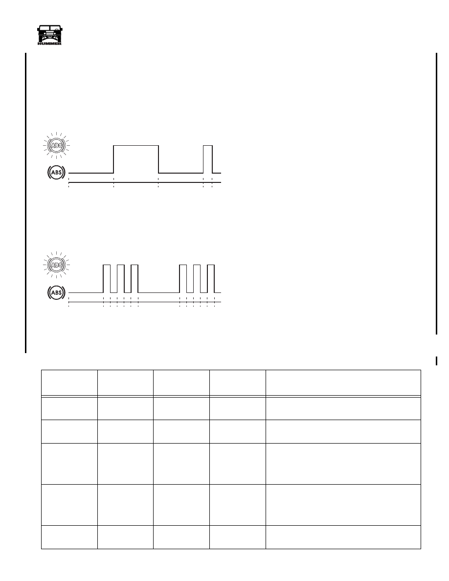
3.
The
start phase
consists of the ABS warning light flashing
in the following sequence (Figure 7-45):
• Pause = 2.5 seconds (long)
• Flash = 2.5 seconds (long)
• Pause = 2.5 seconds (long)
• Flash = 0.5 seconds (short)
Figure 7-45: Blink Code Sequence For Start Phase.
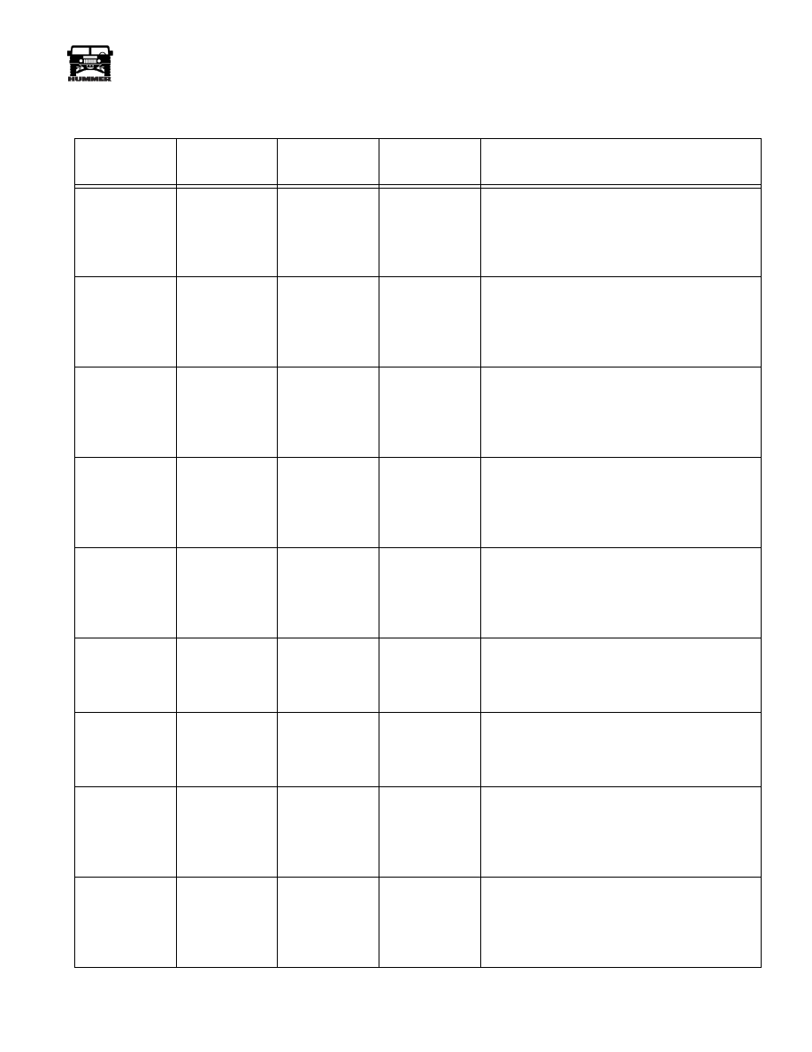
Figure 7-46: Blink Code Sequence For Code 3.3.
4.
The
first part
of the code number (Figure 7-46:): A pause
of 2.5 seconds precedes a series of short flashes. Count the
flashes until the next long pause occurs. The number of
short flashes obtained is the first part of the code number.
5.
The
second part
of the code number: A pause of 2.5
seconds occurs between the first and second parts, before a
series of short flashes occurs. The number of short flashes
forms the second part of the code number.
6.
The sequence of the
start phase
,
first and second parts
will continue until the switch jumper is deactivated.
NOTE:
If you are unsure of the code, do not deactivate the
switch jumper from the DLC because the code for that fault
will be cleared from the memory.
7.
The memory is capable of storing more than one fault. To
search the memory, reconnect the switch jumper and await
the next start phase.
8.
Repeat the procedure until no further faults are stored in
the memory. The memory is cleared when a long pause of
7.5 seconds occurs after the start phase.
Clearing Fault Codes
At the end of a fault code cycle, deactivate the blink code
jumper. The fault code will cycle one more time before the
lamp remains on solid. Turn off the ignition and the fault code
will be cleared from memory.
The fault codes, their causes and repair actions are listed in the
following table.
2.5 sec
2.5 sec
2.5 sec
0.5
sec
8-S07-003
ABS
Warning
Lamp
2.5 sec
8-S07-004
ABS
Warning
Lamp
0.5
sec
0.5
sec
2.5 sec
0.5
sec
0.5
sec
0.5
sec
0.5
sec
Fault Code List - Ignition key “OFF” to test system (except where noted)
Fault Code
Problem Area
Test Pin
Locations
Values
Check/Repair
2-0
ECU internal
failure.
-
-
Replace ECU.
2-1
ECU internal
failure.
-
-
Replace ECU.
2-2
Recirculating
Pump (RCP)
operates contin-
uously.
11 and 27
30 and 27
0 volts
Check the RCP wiring, the pump relay and the
wiring connections. Repair or replace as required.
2-2
RCP does not
operate.
9 and 11
27 and 30
Ignition “ON”
approximate
battery +
voltage.
Check the RCP wiring, the pump relay and fuse
and pump connections. Repair or replace as
required.
2-4
RCP failure
(motor locked).
9, 11 and 12
Ignition “ON”
motor running.
Excessive current failure. If pump does not run
with pins linked, replace modulator.
4-1-00

7-36
Brake System
_____________________________________________________________
®
2-6
Shuttle valve
switch failure.
25 and 27
Brake pedal at
rest 3k
Ω
.
Brake pedal 1/2
down 2k
Ω
.
Brake pedal full
down 1k
Ω
.
If wiring and connections OK, replace modulator.
2-7
Continuous
power to ECU
with ignition
“OFF”.
9 and 27
0 volts.
Less than 0.2
Ω
to chassis
ground.
Check for proper wiring connections, repair as
necessary.
2-8
No voltage to
ABS solenoid
valves.
19 and 27
1 and 27
9 and 27
Link 8 and 9
Ignition “ON”
approximate
battery +
voltage.
Check the valve relay, fuse and wiring. Repair as
necessary.
2-9
Inlet valve
supervision
time exceded.
-
-
Check voltage for normal function. Clear fault.
2-10
Reference
ground inter-
rupted.
31
Less than 0.2
Ω
to chassis
ground.
Repair wiring or connection as necessary.
2-11
Excessive recir-
culation pump
cycle time.
Ignition “ON”
link 9, 11 and
12
-
Check RCP function. Clear fault.
2-12
2-13
2-14
2-15
RF sensor weak
LR sensor weak
LF sensor weak
RR sensor weak
17 and 34
18 and 35
15 and 32
16 and 33
Greater than 0.9
volts AC at one
tire revolution
per second.
Check sensor adjustment. Check geared hub bear-
ing play at halfshaft. Adjust or repair as necessary.
3-0
Open circuit
between ECU
and
right front
inlet
solenoid
valve or wiring.
6 and 27
5.0-7.5
Ω
Check electrical resistance of affected valve wir-
ing to ground at the ECU connector and at the
modulator connector. Repair wiring or replace
modulator as necessary.
3-1
Open circuit
between ECU
and
right front
outlet
solenoid
valve or wiring.
7 and 27
3.0-5.0
Ω
Check electrical resistance of affected valve wir-
ing to ground at the ECU connector and at the
modulator connector. Repair wiring or replace
modulator as necessary.
3-2
Open circuit
between ECU
and
left front
inlet
solenoid
valve or wiring.
23 and 27
5.0-7.5
Ω
Check electrical resistance of affected valve wir-
ing to ground at the ECU connector and at the
modulator connector. Repair wiring or replace
modulator as necessary.
Fault Code List - Ignition key “OFF” to test system (except where noted)
Fault Code
Problem Area
Test Pin
Locations
Values
Check/Repair
____________________________________________________________
Brake System 7-37
®
05745159
3-3
Open circuit
between ECU
and left front
outlet
solenoid
valve or wiring.
24 and 27
3.0-5.0
W
Check electrical resistance of affected valve wir-
ing to ground at the ECU connector and at the
modulator connector. Repair wiring or replace
modulator as necessary.
3-4
Open circuit
between ECU
and right rear
inlet
solenoid
valve or wiring.
4 and 27
5.0-7.5
W
Check electrical resistance of affected valve wir-
ing to ground at the ECU connector and at the
modulator connector. Repair wiring or replace
modulator as necessary.
3-5
Open circuit
between ECU
and right rear
outlet
solenoid
valve or wiring.
5 and 27
3.0-5.0
W
Check electrical resistance of affected valve wir-
ing to ground at the ECU connector and at the
modulator connector. Repair wiring or replace
modulator as necessary.
3-6
Open circuit
between ECU
and left rear
inlet
solenoid
valve or wiring.
21 and 27
5.0-7.5
W
Check electrical resistance of affected valve wir-
ing to ground at the ECU connector and at the
modulator connector. Repair wiring or replace
modulator as necessary.
3-7
Open circuit
between ECU
and left rear
outlet
solenoid
valve or wiring.
22 and 27
3.0-5.0
W
Check electrical resistance of affected valve wir-
ing to ground at the ECU connector and at the
modulator connector. Repair wiring or replace
modulator as necessary.
3-8
Open circuit
between ECU
and RCP relay
1.
11 and 27
30 and 27
Ignition “ON”
approximate
battery +
voltage.
If pump does not run, check wiring from pin 11.
3-9
Open circuit
between ECU
and RCP relay
2.
12 and 27
Ignition “ON”
approximate
battery +
voltage.
If pump does not run, check wiring from pin 12.
4-0
Short circuit to
ground between
ECU and right
front inlet
sole-
noid valve.
6 and 27
5.0-7.5
W
Check electrical resistance of affected valve wir-
ing to ground at ECU connector and at modulator
assembly as necessary.
4-1
Short circuit to
ground between
ECU and right
front outlet
solenoid valve.
7 and 27
3.0-5.0
W
Check electrical resistance of affected valve wir-
ing to ground at ECU connector and at modulator
assembly as necessary.
Fault Code List
Ignition key “OFF” to test system (except where noted)
Fault Code
Problem Area
Test Pin
Locations
Values
Check/Repair
7-38
Brake System
_____________________________________________________________
®
4-2
Short circuit to
ground between
ECU and left
front inlet
sole-
noid valve.
23 and 27
5.0-7.5
W
Check electrical resistance of affected valve wir-
ing to ground at ECU connector and at modulator
assembly as necessary.
4-3
Short circuit to
ground between
ECU and left
front outlet
solenoid valve.
24 and 27
3.0-5.0
W
Check electrical resistance of affected valve wir-
ing to ground at ECU connector and at modulator
assembly as necessary.
4-4
Short circuit to
ground between
ECU and right
rear inlet
sole-
noid valve.
4 and 27
5.0-7.5
W
Check electrical resistance of affected valve wir-
ing to ground at ECU connector and at modulator
assembly as necessary.
4-5
Short circuit to
ground between
ECU and right
rear outlet
solenoid valve.
5 and 27
3.0-5.0
W
Check electrical resistance of affected valve wir-
ing to ground at ECU connector and at modulator
assembly as necessary.
4-6
Short circuit to
ground between
ECU and left
rear inlet
sole-
noid valve.
21 and 27
5.0-7.5
W
Check electrical resistance of affected valve wir-
ing to ground at ECU connector and at modulator
assembly as necessary.
4-7
Short circuit to
ground between
ECU and left
rear outlet
solenoid valve.
22 and 27
3.0-5.0
W
Check electrical resistance of affected valve wir-
ing to ground at ECU connector and at modulator
assembly as necessary.
4-8
Short circuit to
ground between
ECU and RCP
relay 1.
11 or 30 and 27
Open circuit
Check wiring to pump relay and pump connector
through pump. Repair wiring or replace modula-
tor as necessary.
4-9
Short circuit to
ground between
ECU and RCP
relay 2.
12 and 27
Open circuit
Check wiring to pump relay and pump connector
through pump. Repair wiring or replace modula-
tor as necessary.
4-12
Right front
wheel speed
sensor open cir-
cuit.
17 and 34
500-2000
W
Check electrical resistance of affected sensor and
wiring at ECU connector and at harness plugs.
Repair wiring or replace sensor as necessary.
Fault Code List
Ignition key “OFF” to test system (except where noted)
Fault Code
Problem Area
Test Pin
Locations
Values
Check/Repair
Нет комментариевНе стесняйтесь поделиться с нами вашим ценным мнением.
Текст