Hummer H1 (2002+). Manual — part 118
____________________________________________________________
Brake System 7-31
®
05745159
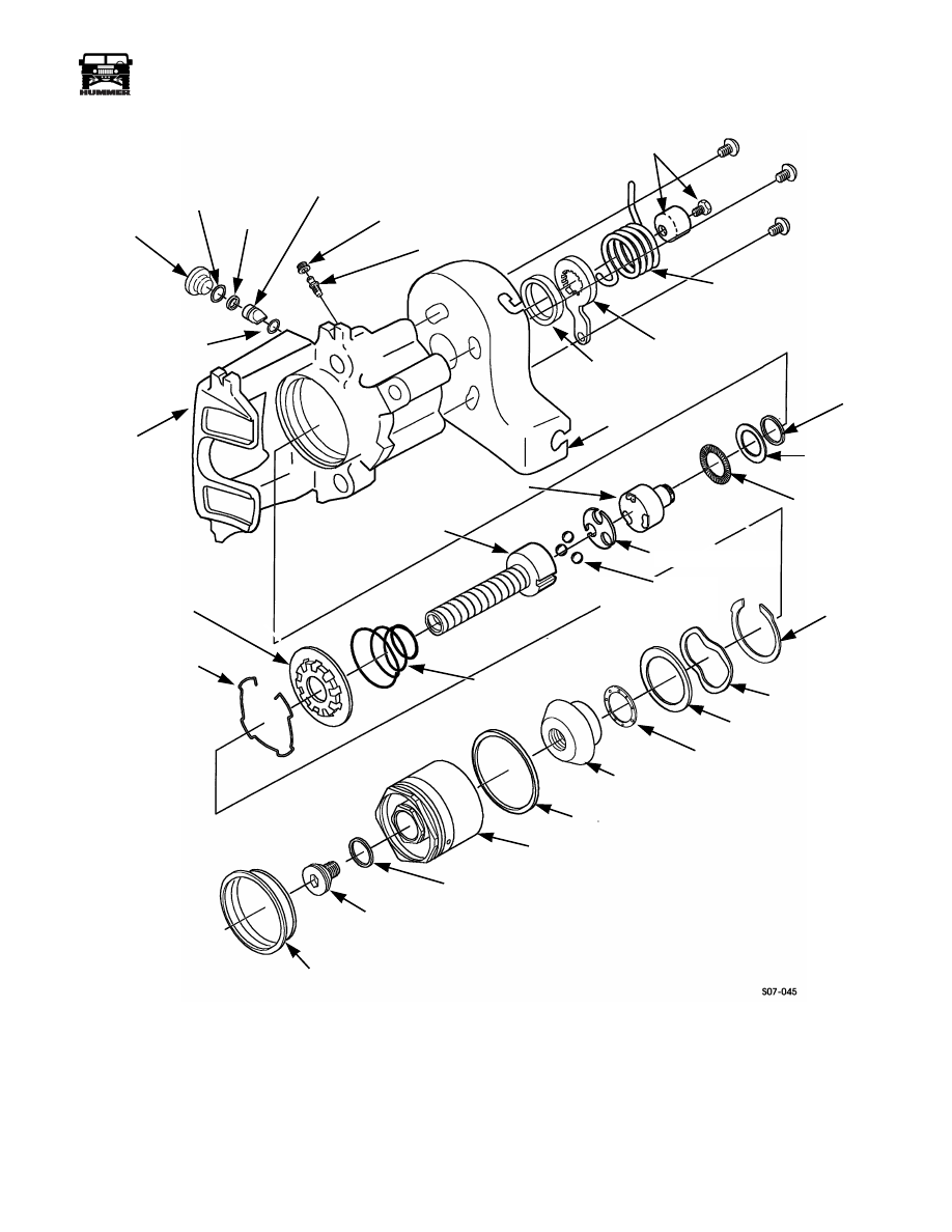
Figure 7-37: Rear Caliper
O-RING
O-RING
BLEEDER SCREW CAP
BLEEDER SCREW
ACTUATOR SHAFT
DUST SEAL
LEVER
SPRING
THRUST SCREW
RETAINING RING
THRUST SCREW
SPRING SHIELD
THRUST SCREW
SPRING
THRUST SCREW
ACTUATOR
O-RING
BEARING
THRUST
ACTUATOR SHAFT
PISTON DUST BOOT
O-RING
PISTON RETAINING SCREW
CALIPER PISTON
PISTON SEAL
SHAFT
RACE
PLUG
SPACER
THRUST SCREW
CENTERING PIN
LEVER RETAINER
AND BOOT
PARKING
BRAKE
LEVER
RETURN
CABLE
HOUSING
BEARING
ACTUATOR SHAFT
BEARINGS
RETAINING
WAVE WASHER
BEARING RACE
CONE CLUTCH
THRUST BEARING
RING
CALIPER
BEARING PLATE

7-32
Brake System
_____________________________________________________________
®
BRAKE ROTOR
Cleaning and Inspection
NOTE:
Clean all components, examine for wear or damage,
and replace if necessary (Figure 7-38).
1.
Remove brake rotor.
NOTE:
Clean rusted or scaled rotor braking surfaces before at-
tempting inspection or measurement.
2.
Mount rotor in brake lathe and turn while cleaning
surfaces with abrasive crocus cloth.
3.
Inspect rotor for heat checks, nicks, broken cooling fins,
scoring, discoloration, and pitting. It is not recommended
that rotors be turned when spotted or heat checked.
Figure 7-38: Brake Rotor and Cooling Fins
NOTE:
Clean debris from cooling fins if necessary.
REFINISHING BRAKE ROTORS
Refinish rotors only under the following circumstances:
1.
There is a complaint of brake pulsation.
2.
There is excessive scoring.
Brake rotors have a minimum thickness dimension cast into
them. This dimension is the minimum wear dimension and not
a refinish dimension. Do not use a brake rotor that will not
meet the dimensions shown in the specifications. Original
equipment rotors are finished to 0.25-1.27 micrometers (10-50
microinches).
Accurate control of rotor tolerances is necessary for the proper
performance of disc brakes. Machining should be done only
with precision equipment. Service the machining equipment on
a regular basis following the manufacturer’s recommended
maintenance procedures.
When you refinish rotors, make sure the attaching adapters,
tool holders, vibration dampeners, and tool bits are in good
condition. Always use sharp cutting tools or bits and use only
replacement cutting bits recommended by the equipment man-
ufacturer. Dull or worn tools leave a poor surface finish that
will affect initial brake performance. Vibration dampening at-
tachments should always be used when refinishing braking sur-
faces. These attachments eliminate tool chatter to allow for a
better surface finish. Make sure these adaptors are clean and
free of nicks. The optional swirl pattern finish will provide the
best initial braking effectiveness. For this, use a sanding disc
power tool with 120 grit disc for about 10 seconds per side.
Checking Lateral Runout
1.
Mount dial indicator with stylus contacting rotor surface 1
in. (25 mm) in from outer edge (Figure 7-39).
2.
Turn rotor 360° and note total indicator reading (TIR).
If lateral runout exceeds 0.004 in. (0.10 mm) TIR, replace or
refinish rotor.
Figure 7-39: Checking Rotor for Lateral Runout
Checking Thickness Variation
1.
Measure thickness variation of rotor with micrometer at
four equally-spaced points around rotor. Measure 1 in. (25
mm) in from outer edge (Figure 7-40).
2.
If thickness variation exceeds 0.005 in. (0.13 mm), replace
or refinish rotor.
Refinishing
1.
Mount rotor on brake lathe and refinish surface.
2.
Replace rotor if refinishing causes rotor to fall below
minimum thickness of 0.815 in. (20.7 mm).
3.
Install brake rotor.
Figure 7-40: Checking Rotor Thickness
BRAKE ROTOR
COOLING FINS
ROTOR
ROTOR

____________________________________________________________
Brake System 7-33
®
05745159
PARKING BRAKE LEVER ADJUSTMENT
Adjustment
1.
Adjust linkage.
2.
Put transmission in PARK, chock wheels, and release
parking brake handle.
3.
Turn adjusting knob clockwise as tightly as possible by
hand (Figure 7-41).
Figure 7-41: Parking Brake Lever Location
4.
Apply parking brake handle.
5.
If parking brake cannot be applied, turn adjusting knob
counterclockwise until parking brake can be applied.
6.
Test parking brake.
a.
Remove chocks.
b.
Depress service brake pedal and start engine.
c.
Place transfer case shift lever in “H” (high) and trans-
mission shift lever in “D” (drive).
d.
Slowly let up on service brake pedal. Parking brake
should hold vehicle stationary.
CAUTION:
The HUMMER is equipped with DOT 3 brake
fluid.
Do not mix with other brake fluids
. Failure to use the
proper brake fluid will damage brake system.
NOTE:
After operating in mud or sand, use a low pressure wa-
ter source to ensure that the parking brake pads, rotor, pad-ro-
tor contact areas, actuating lever, and spring are thoroughly
cleaned of mud, sand, or other debris. Lubricate actuating lever
as soon as possible (Figure 7-42).
Figure 7-42: Spring and Actuating Lever
for Parking Brake
PARKING BRAKE SWITCH REPLACEMENT
Removal
1.
Disconnect the two harness leads from the switch leads
(Figure 7-43).
2.
Remove the switch from the parking brake lever.
Installation
1.
Install the switch on the parking brake lever (Figure 7-43).
2.
Connect two switch leads to the harness leads.
3.
Ensure parking brake switch operates properly.
Figure 7-43: Parking Brake Switch
TRANSMISSION
TRANSFER CASE
ADJUSTING
PARKING BRAKE
LEVER
SHIFT LEVER
HANDLE
KNOB
SHIFT
SPRING
ACTUATING LEVER
SWITCH LEADS
HARNESS LEADS
SWITCH
PARKING BRAKE LEVER
PARKING BRAKE ROD

7-34
Brake System
_____________________________________________________________
®
ANTI-LOCK BRAKE SYSTEM (ABS) AND AUTO-
MATIC TRACTION CONTROL, TORQTRAC 4
™
(TT4
™
)
System Description
The ABS/TT4 is a hydraulic add-on system consisting of:
• Hydraulic modulator and pump assembly
• Electronic control unit
• Four wheel speed sensors
• ABS and TT4 warning lights
The add-on ABS/TT4 system is a four channel brake pressure
modulation system fitted additional to the standard brake sys-
tem. TT4 uses ABS and standard brake components to auto-
matically control traction at the wheels when accelerating on
low friction surfaces.
System Operation
ABS/TT4 system warning lights located in the status center of
the instrument panel illuminate when there is a problem with
the system. The lamps also illuminate during the initial key-on
for a system self check and bulb test sequence. After key-on
the ABS lamp will shine for approximately three seconds then
go out and remain out unless there is a fault in the system or the
ignition is cycled. The TT4 lamp will shine for three seconds
then go out until there is a problem with the system
(Figure 7-44). The TT4 lamp will flash during an overheat pe-
riod due to extended continuous use. Whenever a lamp is lit
due to a failure in the system, ABS and TT4 will be shut down
partially or wholly, depending on the nature of the fault.
Figure 7-44: ABS/TT4 Warning Light Sequence.
Anti-lock braking operates by continually sensing the speed of
each wheel. Wheel speed information is transmitted to an Elec-
tronic Control Unit (ECU) which evaluates the information to
determine when any wheel is about to lock. If locking com-
mences, the ECU transmits a control signal to the appropriate
solenoid valve in the modulator controlling hydraulic pressure
to the brake, thus, brake pressure is adjusted to maintain wheel
rotation.
The TorqTrac 4 system uses many of the same components as
the ABS to control wheel spin when accelerating the vehicle on
low friction surfaces. Information from the wheel speed sen-
sors is evaluated by the ECU which determines if a wheel is
loosing traction and spinning. The ECU actuates the modulator
pump to provide hydraulic pressure which is modulated by the
solenoid valves and sent to the brake of the spinning wheel.
This has the effect of transferring the torque to the non-spin-
ning wheel on the higher friction surface. The system has an
overheat protection feature which disables TT4 after 60 sec-
onds of continuous use. This will be indicated by a blinking
TT4 lamp. TT4 will automatically return to normal operation
after a 60 second cool down period.
ABS/TT4 DIAGNOSTICS
Fault Diagnostic Procedure
Faults are stored in the ECU memory in code form. The infor-
mation can be retrieved by initiating and reading a series of
flash and pause sequences (blink codes) on the ABS warning
light or with the Wabco Diagnostic Controller.
Use of the blink code procedure will determine the location of
the fault prior to performing physical wiring and component
tests, thus reducing diagnostic time.
NOTE:
An attempt to initiate the blink code diagnostic may
result in a solid “on” ABS warning lamp without progressing
to the start phase of the diagnostic. If the above condition is
present, remove the ABS Warning Lamp Relay from the exte-
rior fuse box and perform the blink code diagnostic (See Figure
7-59). After repairs are completed, replace the warning lamp
relay in the socket.
Blink Code Procedure
To initiate the blink code procedure, connect the blink code
switch jumper J–44237
to the Diagnostic Link Connector
(DLC) of the vehicle. The jumper allows you to short pin 4 to
pin 15 of the DLC.
1.
Switch on the ignition, the ABS warning light will illumi-
nate and extinguish if there are no active faults.
2.
Five seconds after connecting the switch jumper, the ABS
warning light will extinguish, indicating the start of the
blink code cycle.
3 sec
ABS
Warning
Lamp
T T4 Info
Lamp
8-S07-002
ignition
on
T T4
3 sec
4-1-00
Нет комментариевНе стесняйтесь поделиться с нами вашим ценным мнением.
Текст