Hummer H1 (2002+). Manual — part 203
______________________________________________________
Electrical System 12-39
®
05745159
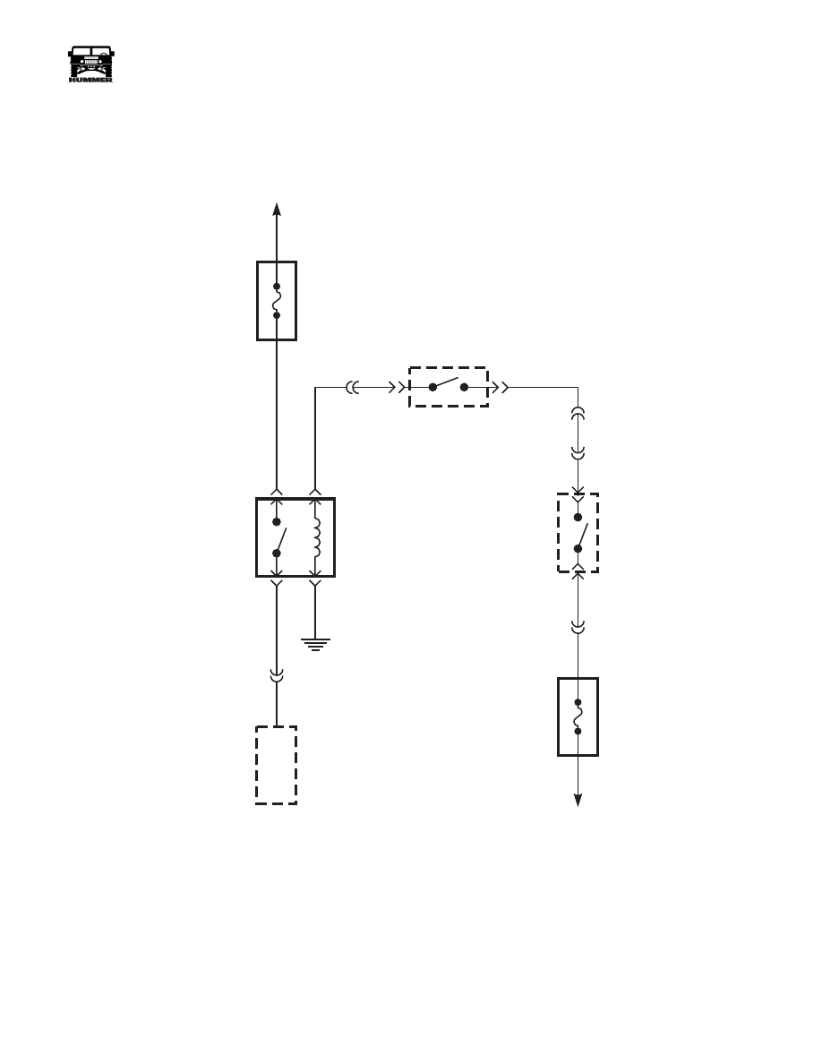
Figure 2-71: Starter System Schematic
MAXIFUSE
#1 40A
EXTERIOR
STARTER
RELAY
37
YEL
58 BLK
32 L
T
BLU
STARTER
SOLENOID
32 L
T
BLU
NEUTRAL
SAFETY
SWITCH
IGNITION
SWITCH
33 WHT
C4-1
C2-13
C1-6
MAXIFUSE
#8 40A
EXTERIOR
C1-7
TO
BATTERY
C2-12
9-S12-087.2
4-1-00
Section 12 Electrical System

12-40
Electrical System
_______________________________________________________
®
Glow Plugs Inoperative
Step
Action
Value
Yes
No
1
Before clearing any DTC’s, use the scan tool Cap-
ture Info to save the Freeze Frame and Failure
Records for reference. The PCM’s data is deleted
once the Clear Info function is used.
Did you perform the On-Board Diagnostic (OBD)
System Check?
Go to step 2.
2
If DTC P0380 is set after a PCM reflash.
Connect a scan tool. Turn the ignition ON leaving
the engine OFF. Observe the Glow Plug System
Type parameter on the scan tool.
Does the scan tool display the Glow Plug System
Type as California?
Go to step 3.
Go to (LINK-
GO TO-
REPAIR-
609502) Glow
Plug System
Type Relearn
3
Connect a scan tool. Turn the ignition ON leaving
the engine OFF. Use the scan tool to command
the glow plugs ON and OFF. Observe the Glow
Plug System Type parameter on the scan tool.
Does the digital multimeter (DMM) display a
voltage near the first specified value with the glow
plug commanded ON and near the second speci-
fied value with the glow plug commanded OFF?
5.0-5.6 Volts
0.9-1.5 Volts
Go to step 7.
Go to step 4.
4
Does the scan tool display a glow plug voltage
greater than the specified value?
5.6 Volts
Go to step 21.
Go to step 5.
5
Does the scan tool display a glow plug voltage
greater than the specified value?
0.3 Volts
Go to step 10.
Go to step 6.
6
Turn the ignition ON leaving the engine OFF.
Touch the battery feed stud on the glow plug con-
troller with an unpowered test lamp connected to
ground.
Is the test light ON?
Go to step 8.
Go to step 25.
7
The DTC is intermittent. If any additional DTC’s
were stored, refer to those table(s).
Were there any additional DTC’s stored?
Go to the appli-
cable DTC
table.
Go to Diagnos-
tic Aids.
8
Disconnect the glow plug relay control connector.
Turn the ignition ON with the engine OFF. With
an unpowered test lamp connected to ground,
probe the glow plug relay harness ignition feed
circuit (CKT 239 PK).
Is the test light ON?
Go to step 9.
Go to step 16.
9
Turn the ignition ON with the engine OFF. Con-
nect an unpowered test lamp to B+, probe the
glow plug relay ground circuit (BK).
Is the test light ON?
Go to step 10.
Go to step 17.
4-1-00

______________________________________________________
Electrical System 12-41
®
05745159
10
Turn the ignition ON with the engine OFF. Verify
that the glow plug relay control harness is discon-
nected. With a DMM connected to ground, probe
the glow plug relay control circuit (466 YL) at the
glow plug relay harness connector. Use a scan
tool to command the glow plugs ON and OFF.
Does the DMM display a voltage near the first
specified value with the glow plugs commanded
ON and near the the second specified voltage with
glow plugs commanded OFF?
9-12 Volts
0 volts
Go to step 12.
Go to step 11.
11
Is the voltage equal to or more than the specified
value all the time?
1.0 Volt
Go to step 23.
Go to step 18.
12
Turn the ignition ON leaving the engine OFF.
Recconect the glow plug relay control harness.
With a DMM connected to ground, backprobe the
glow plug relay signal circuit (506 LB) at the
PCM harness connector. Use a scan tool to com-
mand the glow plugs ON. Observe the DMM
while the glow plugs are commanded ON.
Is the voltage at the specified value?
5.0-5.6 Volts
Go to step 21.
Go to step 13.
13
Turn the ignition OFF. Disconnect the right and
left bank glow plug output circuit connectors at
the glow plug relay. With an unpowered test lamp
connected to B+, probe each circuit.
Does each circuit turn ON the test lamp?
Go to step 26.
Go to step 14.
14
Turn the ignition OFF. Disconnect each glow plug
connector at the glow plug that did not illuminate
the test lamp. With an unpowered test lamp con-
nected to B+, probe the terminal on the glow
plug.
Does each glow plug illuminate the test lamp?
Go to step 26.
Go to step 25.
15
Turn the ignition OFF. Disconnect each glow plug
connector at the glow plug. With an unpowered
test lamp connected to B+, probe each circuit at
the glow plug output connectors.
Is the test lamp OFF at each of the circuits?
Go to step 20.
Go to step 27.
16
Repair an open or a short to ground in the glow
plug relay ignition feed circuit (CKT 239 PK).
Did you complete the repair?
Go to step 30.
17
Repair any opens or poor connections in the glow
plug relay ground circuit (BK).
Did you complete the repair?
Go to step 30.
18
Inspect the glow plug relay control circuit (466
YL) for an open or short to ground. If the glow
plug relay control circuit is open or shorted to
ground, repair as necessary.
Did you find and correct the condition?
Go to step 30.
Go to step 19.
Glow Plugs Inoperative (Cont’d)
Step
Action
Value
Yes
No
4-1-00

12-42
Electrical System
_______________________________________________________
®
19
Inspect the glow plug relay control circuit (CKT
466 YL) for a proper connection at the PCM and
replace the terminal if necessary.
Did you find an improper connection and make
the necessary repair?
Go to step 30.
Go to step 29.
20
Inspect the glow plug relay signal circuit (CKT
506 LB) for an open or short to ground. If the
glow plug relay signal circuit is open or shorted
to ground, repair as necessary.
Did you find and correct the condition?
Go to step 30.
Go to step 28.
21
Inspect the glow plug relay signal circuit (CKT
506 LB) for a proper connection at the PCM and
replace the terminal if necessary.
Did you find an improper connection and make
the necessary repair?
Go to step30.
Go to step 22.
22
Test for a short to voltage in the glow plug relay
signal circuit (CKT 506 LB).
Did you find the improper condition?
Go to step 30.
Go to step 28.
23
Test for a short to voltage in the glow plug relay
control circuit (CKT 466 YL) .
Did you find and correct the condition?
Go to step 30.
Go to step 29.
24
Repair the open or poor connection on the battery
feed circuit.
Did you complete the repair?
Go to step 30.
25
Replace any glow plug that did not illuminate the
test lamp.
Did you complete the repair?
Go to step 30.
26
Repair the open or poor connections in the glow
plug harness.
Did you complete the repair?
Go to step 30.
27
Repair the short to ground in the glow plug har-
ness.
Did you complete the repair?
Go to step 30.
28
Replace the glow plug relay.
Did you complete the repair?
Go to step 30.
29
THE NEW PCM MUST BE PRO-
GRAMMED.Replace the PCM.
Did you complete the repair?
Go to step 30.
Glow Plugs Inoperative (Cont’d)
Step
Action
Value
Yes
No
4-1-00
Нет комментариевНе стесняйтесь поделиться с нами вашим ценным мнением.
Текст