Hummer H1 (2002+). Manual — part 201
______________________________________________________
Electrical System 12-31
®
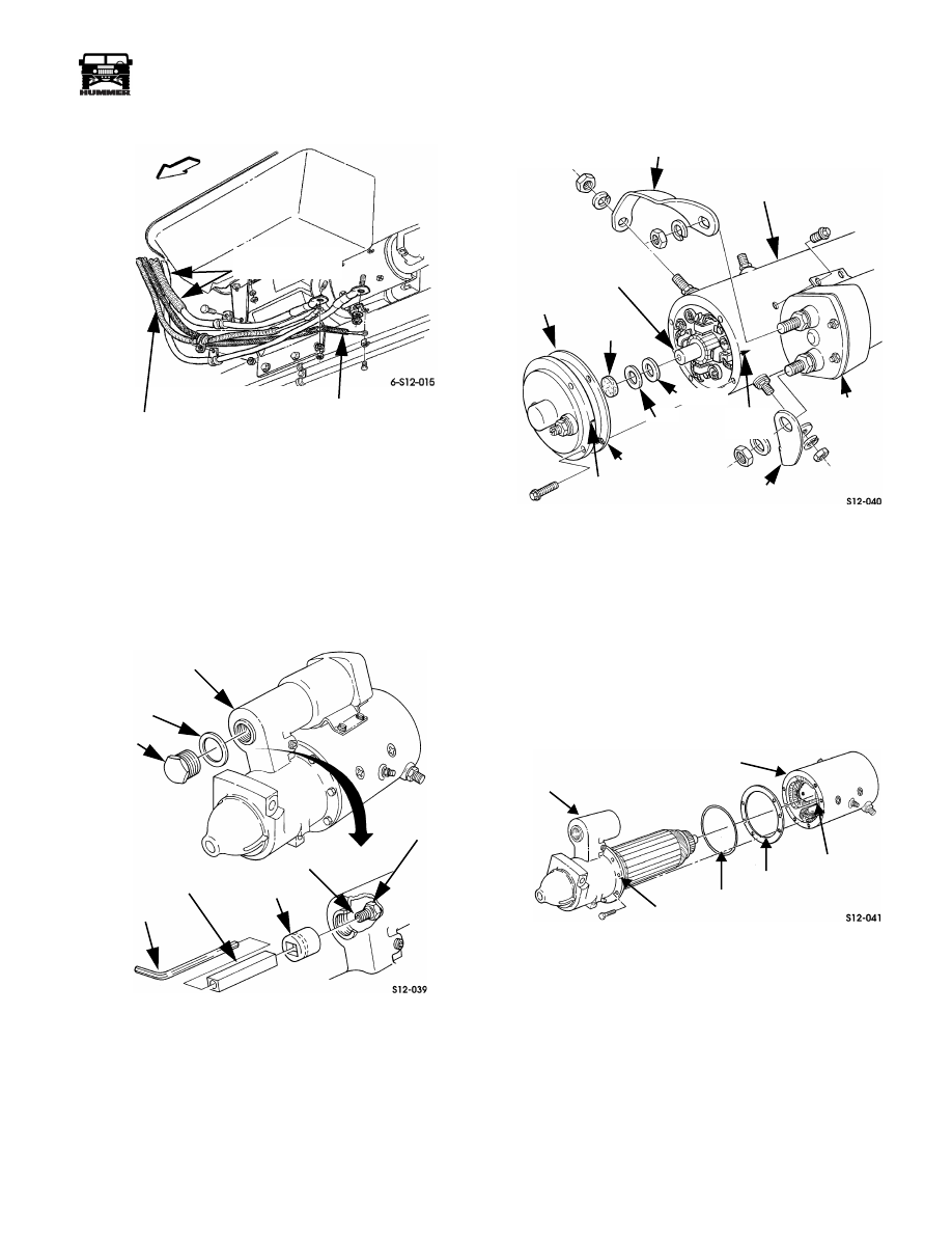
05745159
Figure 12-54: Starter Connections
STARTER OVERHAUL
Disassembly
1.
Remove starter.
2.
Remove plug and gasket from pinion housing (Figure 12-55).
Figure 12-55: Core Shaft Nut Removal
3.
Remove core shaft nut with socket, fabricated socket
holding tool, and hex wrench (Figure 12-55). Holding tool
can be fabricated from suitable size square tube. Or, a
suitable size thin wall, deep socket can be used.
4.
Remove connector nuts and remove solenoid connectors
from frame assembly and solenoid (Figure 12-56).
Figure 12-56: End Plate Removal
5.
Remove solenoid screws and remove solenoid.
6.
Scribe alignment marks on end plate and frame.
7.
Remove end plate bolts and remove end plate and gasket.
8.
Remove thrust washer and spacer from armature shaft.
9.
Remove felt wick from end plate.
10. Scribe alignment marks on pinion housing and frame
(Figure 12-57).
Figure 12-57: Frame Removal
11. Remove screws attaching pinion housing to frame.
12. Remove frame, gasket, and O-ring from pinion housing.
13. Remove two plugs and pin from pinion housing and shift
lever (Figure 12-58).
TO GLOW PLUG
CONTROLLER
SOLENOID
WIRE
STARTER CABLES
(FROM BATTERY)
PINION HOUSING
GASKET
PLUG
LOCKNUT
CORE SHAFT
SOCKET HOLDING
TOOL
HEX WRENCH
SOCKET
SOLENOID
CONNECTOR
FRAME
SOLENOID
MARK
SPACER
FELT
WICK
ARMATURE
SHAFT
GASKET
SOLENOID
CONNECTOR
THRUST
WASHER
END
PLATE
SCRIBE
MARK
SCRIBE
PINION
HOUSING
MARK
O-RING
GASKET
FRAME
SCRIBE
MARK
SCRIBE
4-1-00
12-32
Electrical System
_______________________________________________________
®
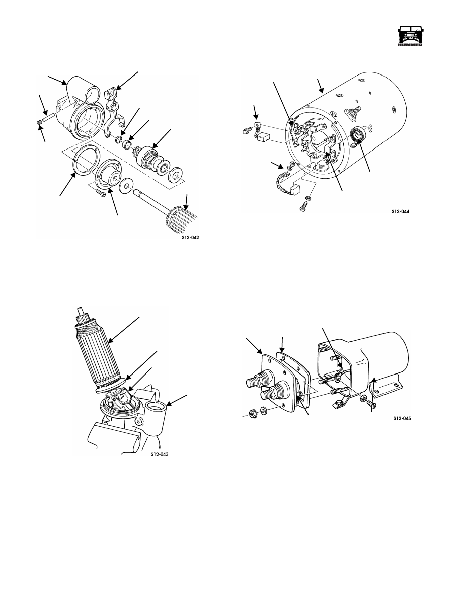
Figure 12-58: Starter Drive Disassembly
14. Clamp pinion housing in vise and remove screws from end
plate and pinion housing (Figure 12-59).
15. Slide armature, end plate, and shift lever out of pinion
housing.
Figure 12-59: Armature Removal/Installation
16. Remove snap ring and pinion stop from armature shaft,
and slide clutch off armature shaft (Figure 12-58).
17. Remove washer and plate from armature shaft (Figure 12-58).
18. Remove gasket from armature plate.
19. Remove nuts, lockwashers, screws, copper washers, and
negative brush leads from frame. Remove brushes from
brush holders (Figure 12-60).
Figure 12-60: Brush and Holder
Removal/Installation
20. Remove screws and positive brush leads from field coil
brackets. Then remove brushes from holders.
21. Remove springs from brush holders.
22. Remove nut and lockwasher assemblies and rubber
washers from solenoid housing. Discard rubber washers
(Figure 12-61).
Figure 12-61: Solenoid Housing
Disassembly/Reassembly
23. Pull cover away from solenoid housing and remove screw
and washer from lug on cover and series winding lead.
24. Remove cover and gasket from solenoid housing.
25. Holding core shaft, remove locknut, washer, and contact
from core shaft (Figure 12-62).
26. Remove and separate spring from core shaft and washer.
27. Remove snap ring, spring retainer, spring, spring retainer,
rubber boot, and washer from core shaft (Figure 12-62).
PLUG (2)
PIN
PINION
HOUSING
SHIFT LEVER
SNAP RING
PINION STOP
CLUTCH
ARMATURE
ARMATURE
GASKET
PLATE
ARMATURE
SHIFT LEVER
PINION
HOUSING
ARMATURE
PLATE
FRAME
FIELD COIL
BRACKET
POSITIVE
BRUSH LEAD
NEGATIVE
BRUSH LEAD
BRUSH
HOLDER
SPRING
COVER
GASKET
SERIES
LUG
SOLENOID
HOUSING
WINDING LEAD
4-1-00
______________________________________________________
Electrical System 12-33
®
05745159
Figure 12-62: Solenoid Components
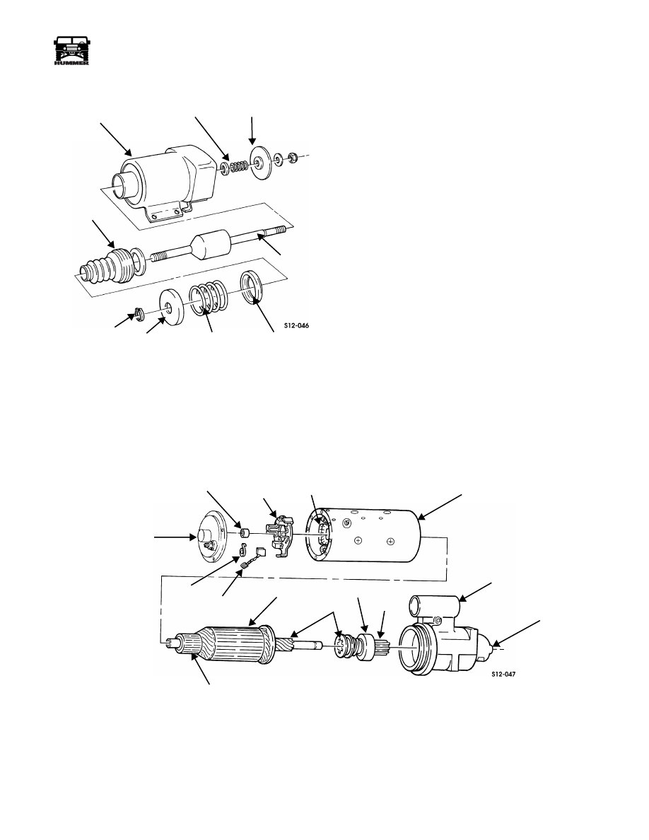
Inspection
Inspect clutch for broken spring, damaged gear or splines, and
non-lockup. Replace clutch if damaged (Figure 12-63).
Inspect brushes for cracks, roughness, galling, wear, or dam-
aged lead. If one brush length is less than 0.315 in. (8 mm) or
has other damage, replace all brushes as a set.
Inspect springs for breaks, distortion, or other damage. Replace
any damaged springs.
Inspect bearings in head end and pinion housing for cracks,
roughness, galling, or damage. Replace bearings if defective
(Figure 12-63).
Inspect pinion housing for cracks, damaged pinion bearing,
and damaged threads. Repair minor thread damage. Replace
starter if otherwise damaged.
Inspect commutator for damage due to arcing (burned spots
and pitting), damaged shaft, splines, or threads. Replace starter
if commutator is damaged.
Test armature, field coils, and brush holders for shorts,
grounds, and open circuits with an armature tester. Replace
starter if any one of these parts is defective.
Inspect core spring, core shaft, and rubber boot for damage.
Replace parts if damaged (Figure 12-64).
Inspect contact for burns or damage. Replace contact if burned
or damaged.
Inspect housing of frame assembly, head end, and solenoid
housing for cracks or damage. Replace starter if any part is
damaged (Figures 12-64 and 12-65).
Figure 12-63: Starter Components
SOLENOID
HOUSING
SPRING
CONTACT
CORE
SHAFT
SPRING
RETAINER
SPRING
SNAP RING
BOOT
SPRING
RETAINER
END PLATE
BEARING
BRUSH
HOLDER
FIELD
COIL
FRAME ASSEMBLY
SPRING
BRUSH
COMMUTATOR
ARMATURE
SPLINES
CLUTCH
GEAR
PINION HOUSING
BEARING
(IN HOUSING)
4-1-00

12-34
Electrical System
_______________________________________________________
®
Figure 12-64: Solenoid Components
Starter Assembly
1.
Assemble washer, rubber boot, spring retainer, spring, and
spring retainer on core shaft and secure with snap ring
(Figure 12-61).
2.
Place core shaft assembly in solenoid housing.
3.
Install washer, spring, contact, washer and locknut on core
shaft.
4.
Place gasket on cover and secure series winding lead to
lug with screw and washer (Figure 12-61).
5.
Install cover and gasket on solenoid housing and secure
with four rubber washers and nut and lockwasher
assemblies.
6.
Install negative brushes and positive brushes in brush
holders and retain with four springs (Figure 12-60).
7.
Connect positive brush leads to field coil brackets with
two screws.
8.
Connect negative brush leads to frame with copper
washers, screws, lockwashers, and nuts.
9.
Cover negative lead screw heads with silicone adhesive
sealant.
10. Apply chassis grease to armature shaft, shift lever studs,
groove of clutch, and inside diameter of end plate
(Figure 12-63).
11. Place washer, end plate, and gasket on armature shaft.
12. Place washer, clutch, and pinion stop on armature shaft
and retain with snap ring. Position armature and shift lever
in position shown for installation (Figure 12-59).
13. Install shift lever on clutch with shift lever studs engaged
in clutch groove.
14. Start shift lever into pinion housing as armature is
positioned in large bore of pinion housing. Then install
screws through armature plate into pinion housing.
Tighten screws to 40 lb-in. (5 N•m) (Figure 12-59).
15. Insert pin through pinion housing and shift lever. Then
install two plugs in pinion housing (Figure 12-58).
16. Install O-ring and gasket in pinion housing (Figure 12-66).
17. Coat end plate-to-frame screws with adhesive sealant.
CAUTION: As armature is inserted into frame assembly, care-
fully align brushes on commutator. Brushes chip and break
easily.
18. Align scribe marks on frame and pinion housing, and
install armature and pinion housing in frame assembly.
Install and tighten screws to 50 lb-in. (6 N•m).
19. Saturate felt wick with engine oil and install in end plate
(Figure 12-65).
Figure 12-65: Starter End Plate Installation
20. Install spacer and thrust washers on armature shaft.
21. Align scribe marks on end plate and frame and install end
plate. Tighten end plate screws to 25 lb-in. (3 N•m).
22. Coat threads of end plate screws with adhesive sealant.
23. Install end plate screws.
24. Check end play as described in following procedure.
25. Coat ribbed area of core shaft boot with lithium grease
(Figure 12-67).
26. Align end of core shaft in hole in shift lever and install
solenoid on frame. Tighten solenoid screws to 50 lb-in. (6
N•m).
27. Install core shaft nut. Tighten nut with socket, fabricated
tool, and hex wrench (Figure 12-55)
CORE
SPRING
RUBBER
BOOT
SOLENOID
HOUSING
CONTACT
SPRING
CORE
SHAFT
FRAME
ASSEMBLY
THRUST
WASHER(S)
FELT
WICK
MARK
GASKET
SPACER
MARK
SCRIBE
SCRIBE
END
PLATE
4-1-00
Нет комментариевНе стесняйтесь поделиться с нами вашим ценным мнением.
Текст