Hummer H1 (2002+). Manual — part 83

___________________________________________
Transmission/Transfer Case 5-131
®
05745159
Transmission Cooler Flushing Procedure
Equipment Needed
• J–35944-A cooler flushing tool with included adapters
and J–35944-22 or J–35944-CSE* flushing solution.
• Measuring Cup
• Funnel
• Water Supply (hot water recommended)
• Water Hose (at least 5/8” I.D.)
• Shop Air Supply (with water/oil filters, regulator and
pressure gauge)
• Air Chuck (with clip if available)
• Oil Drain Container
• Five Gallon Pail With Lid
• Eye Protection
• Rubber Gloves
* Do not substitute with solutions that contain alcohol or gly-
col. Use of solutions that contain alcohol or glycol may dam-
age J–35944-A, oil cooler or transmission components.
Preparation
1.
After the repaired or replacement transmission is installed
in the vehicle, do not reconnect the oil cooler pipes.
2.
Remove the fill cap on J–35944-A and fill with 20-21 oz.
(0.6L) of flushing solution. Do not overfill.
3.
Install the fill cap on J–35944-A and pressurize the flusher
can using the shop air supply 80-100 psi (550-700 kPa).
4.
Connect the J–35944-A discharge hose to the oil cooler
return pipe.
5.
Clip the discharge hose onto the oil drain container.
6.
Attach J–35944-A to the undercarriage of the vehicle with
the hook provided and connect the hose from J–35944-A
to the other (feed) oil cooler pipe.
7.
With the water valve on J–35944-A in the “OFF” position,
connect the water hose from the water supply to J–35944-
A.
8.
Turn “ON” the water supply at the water faucet.
Initial Flush
1.
Turn the water valve on J–35944-A to the “ON” position
and allow the water to flow through the oil cooler and
pipes for 10 seconds to remove any remaining transmis-
sion fluid. If water does not flow through the oil cooler and
pipes, the cause of the blockage must be diagnosed and the
plugged component must be repaired or replaced. Con-
tinue with the cooler flushing and flow check procedure
once the blockage is corrected.
2.
Turn the water valve on J–35944-A to the “OFF” position
and clip the discharge hose onto the five gallon pail with a
lid.
3.
Turn the water valve on J–35944-A to the “ON” position
and depress the trigger to mix cooler flushing solution into
the water flow. Use the clip provided on the handle to hold
the trigger down. The discharge will foam vigorously
when the solution is introduced into the water stream.
4.
Flush the oil cooler and pipes with water and solution for
two minutes. During this flush, attach the air supply to the
air valve located on J–35944-A for 3-5 seconds at the end
of every 15-20 second interval to create a surging action.
5.
Release the trigger and turn the water valve on J–35944-A
to the “OFF” position.
Back Flush
1.
Disconnect both hoses from the oil cooler pipes and then
connect them to the opposite oil cooler pipe. This will
allow the oil cooler and pipes to be back flushed.
2.
Repeat steps 3 and 4 of the “INITIAL FLUSH” procedure.
3.
Release the trigger of J–35944-A and allow water only to
rinse the oil cooler and pipes for one minute.
4.
Turn the water valve on J–35944-A to the “OFF” position
and turn “OFF” the water supply at the faucet.
5.
Attach the air supply to the air valve on J–35944-A and
blow out the water from the oil cooler and pipes. Continue
until no water comes out of the discharge hose.
Flow Check
1.
Disconnect both hoses from the oil cooler pipes. Connect
the oil cooler feed pipe to the transmission and the return
pipe to the discharge hose. Clip the discharge hose onto
the oil drain container.
2.
Confirm the transmission is filled with automatic
transmission fluid.
3.
Start the engine with the transmission in “PARK” range
and run until automatic transmission fluid begins to flow
into the oil drain container. Turn off engine, empty oil
drain container and fill transmission with automatic
transmission fluid. Start the engine with the transmission
in “PARK” range and run for 30 seconds. A minimum of
two quarts (1.9 L) must be discharged during this 30
second run time.
If fluid flow is equal to or greater than 2 qt. in 30 seconds,
go to step 4.
If fluid flow is less than 2 qt. in 30 seconds, perform the
following diagnosis:
• Disconnect the oil cooler feed line at the radiator. Con-
nect the discharge hose to the oil cooler feed line. Clip
the discharge hose onto the empty oil drain container.
Start the engine with the transmission in “PARK” range
and run for 30 seconds. A minimum of two quarts (1.9
L) must be discharged during this 30 second run time.
Do the following according to the flow rate:
Insufficient feed flow:
• Inspect the transmission for leaks or blockage.
Sufficient feed flow:
• Inspect the oil cooler return pipe and the oil cooler for
blockages or leaks.
5-132
Transmission/Transfer Case
___________________________________________
®
4.
Remove the discharge hose, reconnect the cooler feed and
return pipes to the transmission and refill the unit to the
proper level. Inspect the transmission oil cooler pipe
connections at the radiator and transmission for leaks.
Cleanup
1.
Disconnect the water supply hose from J–35944-A and
bleed any remaining air pressure from the can. Remove the
fill cap from J–35944-A and return any unused flushing
solution to its container. Rinse J-35944-A with water. Do
not store J–35944-A with flushing solution in it.
2.
After every third use, clean J–35944-A as described in the
instructions included with the tool.
3.
Dispose of any waste water/solution/transmission fluid in
accordance with local regulations.
Transmission Fluid And Filter Replacement
1.
Support transmission/transfer case assembly with jack
positioned under transfer case.
2.
Remove bolts attaching rear mount to transmission
(Figure 5-28).
3.
Remove bolts attaching crossmember to frame brackets
and remove crossmember.
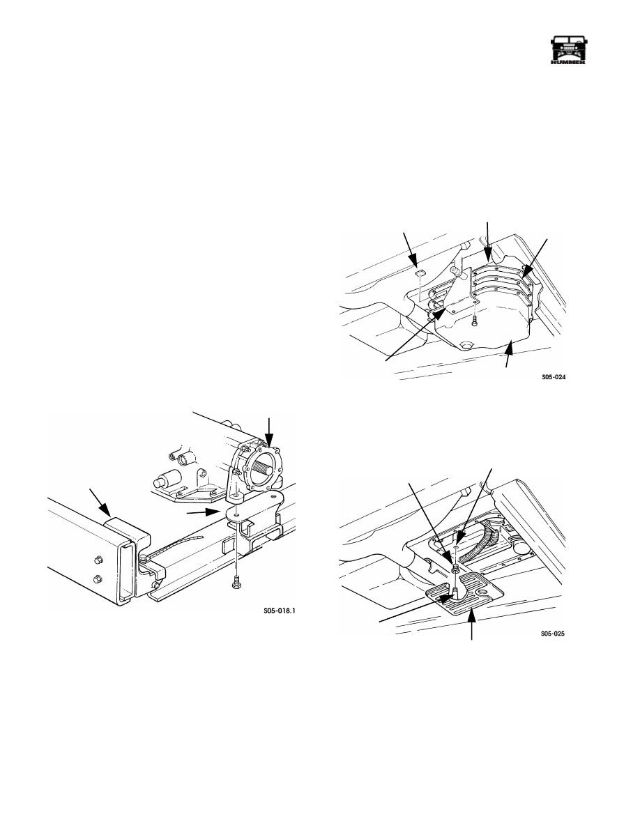
Figure 5-28: Transmission-to-Crossmember
Mounting
4.
Loosen transmission oil pan bolts and allow fluid to drain.
5.
Move shift rod bracket aside and remove pan gasket, and
oil pan (Figure 5-29). Pan gasket is reusable.
6.
Remove oil filter from valve body (Figure 5-30).
7.
Inspect filter seal (Figure 5-30). Undamaged seal is re-
usable.
8.
Remove magnet from oil pan. Then clean pan and magnet.
9.
Install seal in valve body.
10. Insert filter pipe in case with twisting motion. Align filter
with valve body and work into place (Figure 5-30).
11. Position magnet in oil pan.
12. Install gasket on oil pan and install pan on transmission.
Tighten pan bolts to 18 lb-ft (24 N•m) torque.
13. Install rear crossmember and transmission mount.
14. Remove support jack.
15. Refill transmission with Dexron III fluid.
Figure 5-29: Oil Pan Removal/Installation
Figure 5-30: Oil Filter Removal/Installation
REAR
MOUNT
FRAME
BRACKET
ADAPTER
PAN
GASKET
TRANSMISSION
OIL PAN
MAGNET
SHIFT ROD
BRACKET
OIL PAN
SEAL
VALVE BODY
INLET PORT
OIL FILTER
FILTER
PIPE
___________________________________________
Transmission/Transfer Case 5-133
®
05745159
COOLER LINE AND BYPASS VALVE SERVICE
The transmission and transfer case oil cooler lines are replace-
able parts.
The lines consist of metal tubing interconnected by sections of
rubber hose (Figure 5-31). Each of the tube or hose sections
can be replaced separately. It is not necessary to replace com-
plete assemblies.
On Hummers, the cooler lines are fastened to the trans
mission with quick connect fittings. The flared end of the line
fits tightly into the adapter and is secured to the adapter with a
clip. The clip is then secured with a nylon retainer.
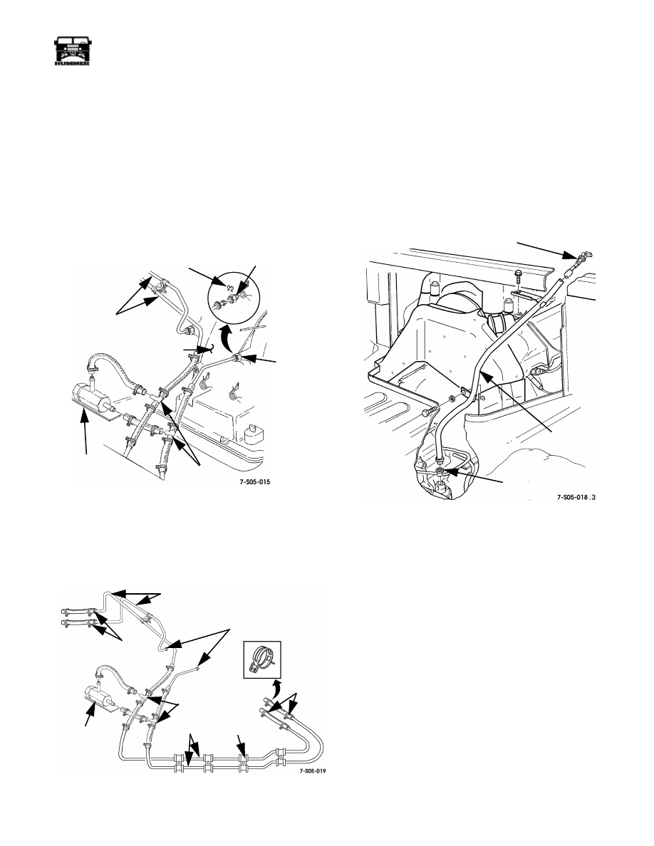
Figure 5-31: Bypass Valve Connections
A bypass valve is used in all Hummer vehicles (Figure 5-32).
The valve limits pressure buildup in the oil cooler and
lines.The bypass valve is attached to the passenger side cross-
member-to-frame bracket bolt. The cooler lines are attached to
body/chassis components with clamps (Figure 5-31).
Figure 5-32: Transmission/Transfer Case Oil Cooler
Line Connection
FILL TUBE REPLACEMENT
1. Remove dipstick from fill tube (Figure 5-33).
2. Remove console and engine cover.
3. Remove bolts attaching fill tube bracket to heat shield and
intake manifold (Figure 5-33).
4. Work fill tube out of transmission.
5. Remove fill tube seal from transmission. Discard if
damaged.
Figure 5-33: Fill Tube Attachment
6. Install fill tube seal in transmission.
7. Push fill tube into transmission.
8. Secure fill tube to the heat shield and intake manifold.
Tighten intake manifoldbolt to 31 lb-ft (42 N•m).
9. Install dipstick in fill tube.
10. Install engine cover and console.
11. Start engine and top off transmission fluid level if
required.
COOLER LINES
(TO TRANSFER CASE)
TRANSMISSION
BYPASS
VALVE
TEE
FITTINGS
NYLON
RETAINER CLIP
ADAPTER
QUICK
CONNECT
FITTING
TO
TRANSFER
CASE
TO
TRANSMISSION
METAL TUBE
TO
COOLER
BYPASS
VALVE
TEE
METAL
TUBE
CHASSIS
CLAMP
FILL TUBE
FILL TUBE SEAL
DIPSTICK
Section 5 Transmission/Trans er Case
5-134
Transmission/Transfer Case
___________________________________________
®
VENT LINE SERVICE
The transmission, transfer case, front and rear hubs, and winch
are all connected to a common vent line system (Figure 5-34).
The main vent lines are plastic while lines from the hubs to the
tee connections consist of rubber hoses. Brass tee fittings are
used at each vent line junction.
The transmission and transfer case vent lines and fittings are all
serviceable parts.
Vent lines or fittings can be replaced individually. It is not nec-
essary to replace all of the lines if only one section is damaged.
In cases where plastic vent line is supplied in bulk quantity, the
required length can be cut to size with a fine tooth hacksaw
blade. Diagonal pliers or similar cutting implements are not
recommended.
If a plastic line proves difficult to install, a small amount of liq-
uid soap can be used as a lubricant. Do not use any other prod-
uct to ease line assembly and installation.
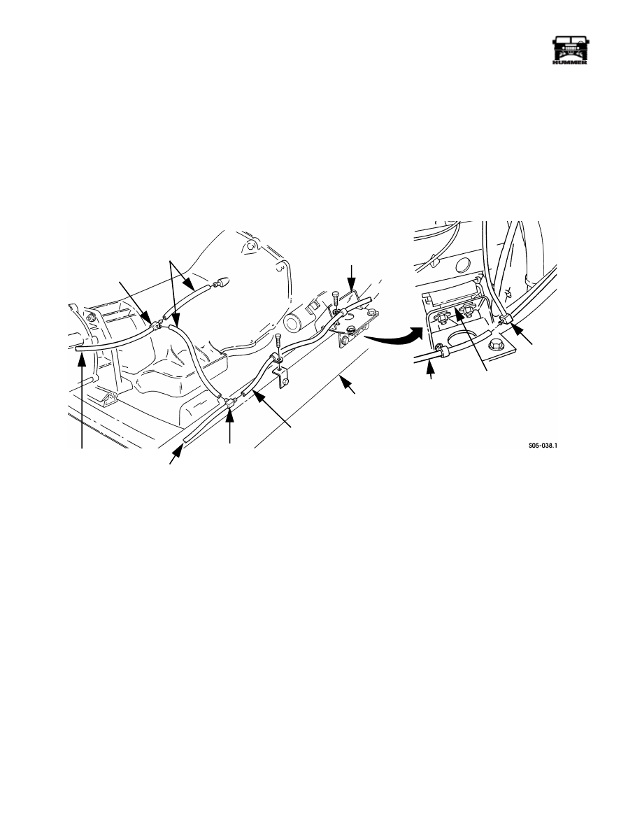
Figure 5-34: Transmission Vent Line
TRANSMISSION
VENT LINES
TEE FITTING
LINE FROM
TRANSFER CASE
TEE FITTING
LINE FROM
REAR HUBS
FRAME RAIL
VENT LINE
TEE FITTING
ENGINE
MOUNTING
BRACKET
ENGINE
MOUNTING
BRACKET
LINE TO FRONT
HUBS AND WINCH
Нет комментариевНе стесняйтесь поделиться с нами вашим ценным мнением.
Текст