Hummer H1 (2002+). Manual — part 84
___________________________________________
Transmission/Transfer Case 5-135
®
05745159
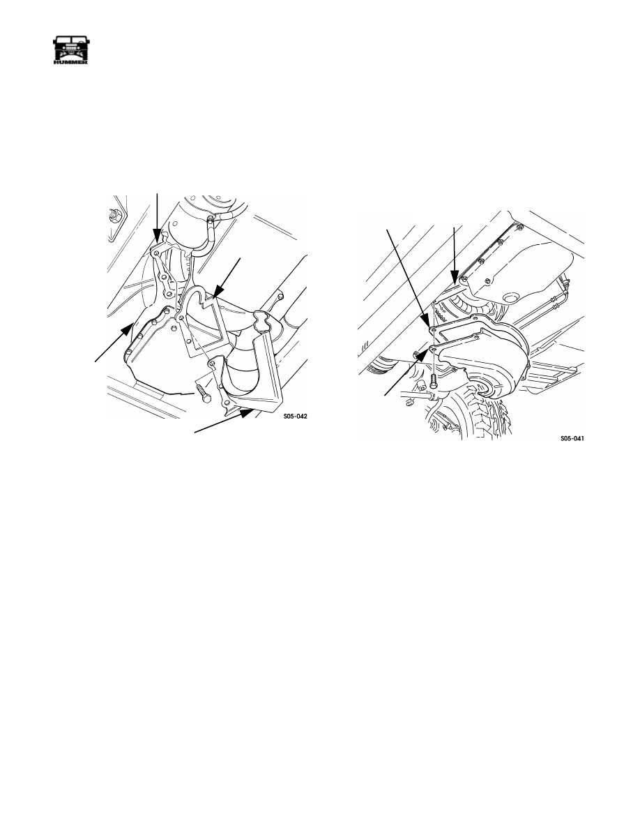
CONVERTER HOUSING UPPER COVER
REPLACEMENT
1.
Remove converter housing upper cover from transmission
flange (Figure 5-35).
2.
Remove gasket from cover.
3.
Clean gasket or sealer remains from transmission flange.
Figure 5-35: Converter Housing Upper Cover
Mounting
4.
Apply sealer to gasket and install gasket on cover.
5.
Install cover on transmission flange.
CONVERTER HOUSING LOWER COVER
REPLACEMENT
1.
Remove crossover pipe.
2.
Remove converter housing upper cover.
3.
Remove lower bolts and remove cover from transmission
(Figure 5-36).
4.
Remove gasket from housing cover.
5.
Clean sealer or gasket remains from transmission flange.
Figure 5-36: Converter Housing Lower Cover
Mounting
6.
Apply sealer to gasket and install on cover.
7.
Apply sealer to housing cover.
8.
Install housing cover on transmission flange.
9.
Install converter housing upper cover.
10. Install crossover pipe.
TRANSMISSION
FLANGE
TRANSMISSION
GASKET
CONVERTER HOUSING
UPPER COVER
GASKET
CONVERTER
HOUSING
LOWER
COVER
TRANSMISSION
FLANGE
5-136
Transmission/Transfer Case
___________________________________________
®
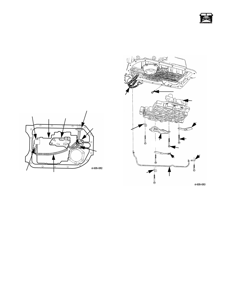
VALVE BODY SWITCH AND SOLENOID
SERVICE
The following electrical components can be replaced once the
oil pan and/or valve body are removed from the transmission
(Figure 5-37):
• 1-2 and 2-3 shift solenoids
• pressure switch
• pressure control solenoid
• converter clutch solenoid
• wiring harness
The park lock actuator components are also accessible after
valve body removal. Refer to Park Lock Component Service.
Figure 5-37: Valve Body Switch and Solenoid
Locations
Valve Body Removal
1.
Remove oil pan and filter. Refer to Fluid and Filter
Replacement procedure in this section.
2.
Remove bolts attaching lube pipe clamp and retainer.
Then carefully remove lube pipe (Figure 5-38).
3.
Disconnect wiring harness from switch and solenoids.
4.
Remove special bolts attaching pressure switch to valve
body and remove switch. Keep special bolts separate and
note position for installation reference (Figure 5-38).
5.
Remove bolts attaching dipstick stop and park detent
spring to valve body and remove stop and spring.
6.
Remove remaining valve body bolts and carefully remove
valve body, spacer plate, and gasket.
CAUTION:
The valve body check-balls are not secured and are
loose. Keep the valve body level and the spacer plate in position
during removal. This will avoid losing or mispositioning the
check-balls. The check-balls are not available separately, they
are available only as part of a complete valve body assembly.
Figure 5-38: Valve Body Removal/Installation
7.
Remove necessary solenoid from valve body. Refer to
Figure 5-37 or Figure 5-39 for solenoid locations.
8.
Remove wiring harness, if it is to be replaced.
CONVERTER
CLUTCH
SOLENOID
WIRING HARNESS
VALVE
BODY
PRESSURE
CONTROL
SOLENOID
PRESSURE
SWITCH
HARNESS
CASE
CONNECTOR
1-2
SHIFT
SOLENOID
2-3
SHIFT
SOLENOID
LUBE
PIPE
CLAMP
LUBE
PIPE
DETENT
SPRING
LUBE
PIPE
RETAINER
VALVE BODY
BOLT (TYPICAL)
SPECIAL
BOLT (6)
PRESSURE
SWITCH
CABLE
CLAMP
DIPSTICK
STOP
VALVE
BODY
PRESSURE CONTROL
SOLENOID SCREEN
WIRING
HARNESS
___________________________________________
Transmission/Transfer Case 5-137
®
05745159
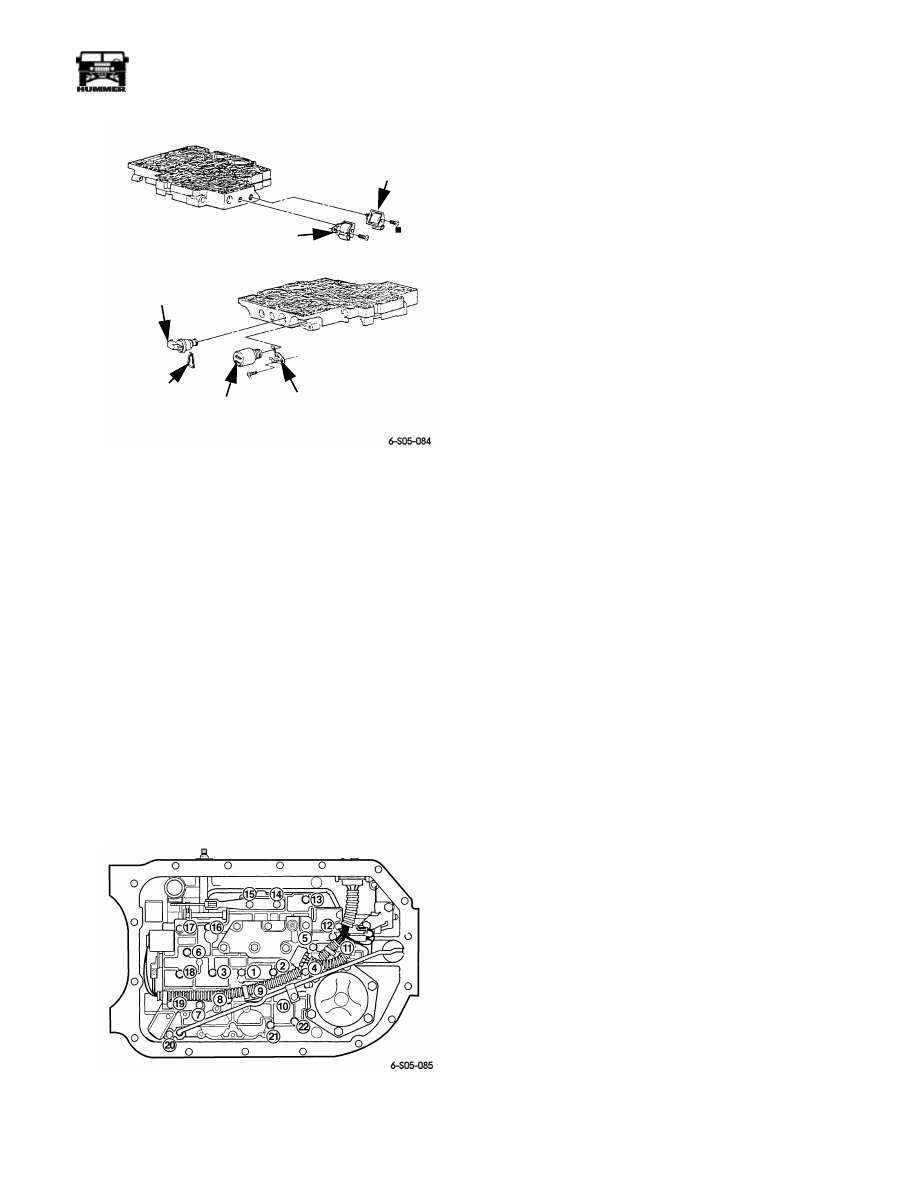
Figure 5-39: Solenoid Identification
Valve Body Installation
1.
Install replacement solenoid or wiring harness as required.
2.
Verify that valve body spacer plate and gasket are in
position. Also be sure check-balls were not displaced.
There should be eight check-balls.
3.
Install valve body guide pins J–25025-B in transmission
case.
4.
Carefully position valve body on guide pins and
transmission case. Install 2-3 bolts to hold valve body in
place and remove guide pins.
5.
Install pressure switch, dipstick stop, harness clamp and
detent spring but do not fully tighten bolts at this time.
6.
Install lube pipe, retainer, and pipe clamp (Figure 5-38).
7.
Tighten valve body bolts to 97 lb-in. (11 N•m) torque.
Start at center and work outward in a spiral pattern
(Figure 5-40).
Figure 5-40: Valve Body Bolt Tightening Sequence
(in Numerical Order)
CAUTION:
The valve body bolts must be tightened to speci-
fied torque and in the indicated pattern. Overtightening or ran-
dom tightening will distort the valve body resulting in valve
bind, cross leakage, and shift problems.
8.
Connect wire harness to solenoids and switch.
9.
Install oil filter and oil pan.
10. Refill transmission with Dexron III.
PARK LOCK COMPONENT SERVICE
The park lock components can be serviced without removing
the transmission.
Access to the park lock components requires removal of the oil
pan and valve body. Part replacement procedure is as follows.
Park Lock Component Replacement
1.
Remove oil pan and valve body as described in this sec-
tion.
2.
Remove nut that retains detent on shaft (Figure 5-41).
Then remove shaft pin.
3.
Remove park pawl bracket bolt and bracket.
4.
Remove detent and actuator rod (Figure 5-41).
5.
Remove park pawl stud, retainer, spring, shaft, and plug
(Figure 5-41).
6.
Clean parts to be reused with solvent, dry with compressed
air, and lubricate with Dexron III.
7.
Install pawl shaft in case. Then install pawl on shaft.
Install new shaft cup plug in case with 5/16 in. (7.9 mm)
diameter rod.
8.
Install pawl retainer and return spring (Figure 5-41).
9.
Assemble detent and actuator rod. Then install rod over
pawl.
10. Install detent shaft and seal. Be sure shaft is properly
seated in detent.
11. Install detent nut on shaft. Tighten nut to 18 lb-ft (24 N•m)
torque.
12. Install shaft pin.
13. Install actuator rod bracket and bolts. Tighten bolts to 18
lb-ft (24 N•m) torque.
14. Install return spring stud.
15. Install valve body, oil filter and oil pan.
16. Refill transmission with Dexron III. Correct fluid level is
at top, or within cross hatch area on dipstick, with fluid
hot, engine idling and transmission in park.
2-3 SHIFT
SOLENOID B
1-2 SHIFT
SOLENOID A
CLAMP
CLIP
PRESSURE
CONTROL
SOLENOID
CONVERTER
CLUTCH
SOLENOID

5-138
Transmission/Transfer Case
___________________________________________
®
Figure 5-41: Park Lock Components
PARK
PAWL
STUD
BRACKET
BOLT (2)
DETENT
NUT
ACTUATOR
ROD
DETENT
SHAFT
PIN
DETENT
SHAFT
SEAL
RETAINER
RETURN
SPRING
CUP
PLUG
PAWL
SHAFT
Нет комментариевНе стесняйтесь поделиться с нами вашим ценным мнением.
Текст