Hummer H1 (2002+). Manual — part 18

____________________________________________________________________
Engine 2-33
¨
05745159
ROCKER ARM, SHAFT, AND PUSHROD SERVICE
Removal
1.
Remove one or both rocker arm covers as needed. Refer to
procedures in this section.
2.
Remove bolts and retainers that attach rocker arm shafts to
cylinder head (Figure 2-36). Note position of bolts for
installation reference. Bolts must be reinstalled in same
threaded holes.
3.
Lift and remove each rocker arm and shaft assembly
(Figure 2-36). Do not intermix assemblies if they will be
reused. Each assembly must be reinstalled in same
position.
4.
Remove pushrods in sequence. Keep them in order of
removal. Also note which end of push rod goes in rocker
arm. This end of rod is heat treated and usually identified
with a paint mark
.
Figure 2-36: Rocker Arm Shafts and Pushrods
PUSHROD
RETAINER
ROCKER ARM AND
SHAFT ASSEMBLIES
SHAFT
ATTACHING
BOLT
2-34
Engine
_____________________________________________________________________
¨
Cleaning and Inspection
Clean the valve train components in parts cleaning solvent.
Carb cleaner or a spray type gasket remover can be used to re-
move stubborn deposits.
Mark position of the rocker arms on the shafts. Remove the
rocker arm retainers with pliers. Then remove the arms and ex-
amine the shafts for wear, grooving, or surface cracks. Check
the rocker arms for cracks at the shaft bores and for wear at the
valve and push rod contact points. Replace worn, or damaged
parts as needed.
Check the pushrods for wear, or distortion. Replace any push
rod exhibiting wear (at either end), or if bent, or kinked.
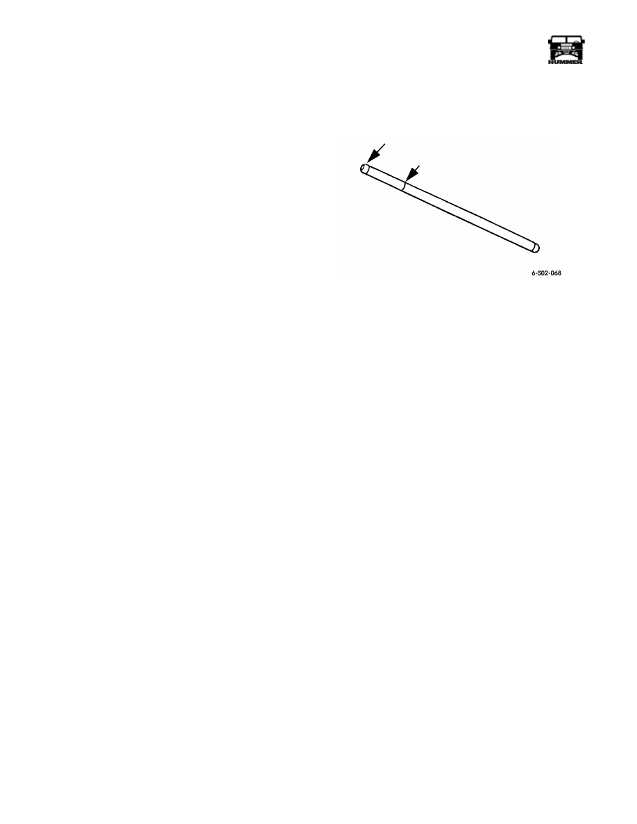
NOTE: The rocker arm end of each pushrod is identified with
a paint stripe. The ball at this end is also coated or heat treated
giving it a distinctive copper color.
Installation
1.
Lubricate all parts with engine oil, or with a quality assem-
bly lube.
2.
Install pushrods in same sequence as when removed.
Verify that heat treated or coated end is facing up toward
rocker arm.
3.
Assemble rocker arms and shaft if necessary. Secure arms
with new retainers but be sure reused arms are installed on
same shafts and in same position. Do not intermix parts.
4.
Index crankshaft and pistons for rocker arm shaft
installation as follows:
a.
Position breaker bar and socket on crankshaft damper
bolt. Do not use starter to rotate crankshaft. Turn shaft
with hand tools only.
b.
Rotate crankshaft counterclockwise, and align mark
on torsional damper with ÒOÓ mark on front cover
timing tab.
c.
Rotate engine counterclockwise an additional 3 1/2
inches (89 mm), measured at mark on torsional
damper. Damper mark should align with water pump
first, lower attaching bolt at this point (Figure 2-43).
5.
Align and install rocker arm and shaft assemblies
(Figure 2-36). Be very sure pushrods are seated in lifters
and in rocker arms.
6.
Install rocker arm shaft retainers and bolts. Tighten bolts
in small increments until snug, with socket and ratchet or
nut runner.
CAUTION: Do not use an air wrench to tighten the bolts. In
addition, stop tightening if the bolts become hard to turn be-
fore they are seated. If this condition occurs, the crankshaft
and pistons are not properly indexed, allowing the valves to
contact the pistons.
7.
Verify that pushrods are properly seated in rocker arms
and lifters. Then final-tighten rocker arm shaft bolts to 41
lb-ft (56 N¥m) torque.
8.
Install rocker covers and intake manifold as described in
this section.
Figure 2-37: Pushrod I.D.
COATED/TREATED END
PAINT MARK
____________________________________________________________________
Engine 2-35
¨
05745159
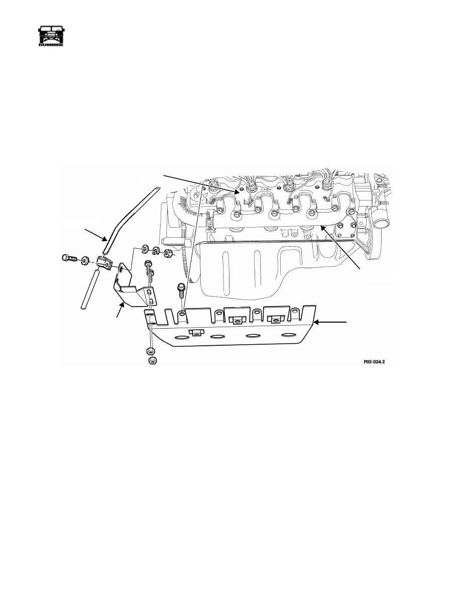
EXHAUST MANIFOLD SERVICE
Right Exhaust Manifold Heat Shield Replacement
Removal
1.
Remove console and engine access cover.
2.
Remove right exhaust manifold rear heat shield screws
and locknuts (Figure 2-38).
3.
Remove shield attaching screws and remove heat shield.
4.
Position heat shield on crossover pipe and exhaust
manifold.
5.
Install heat shield and exhaust manifold on cylinder head
and tighten capscrews to 25 lb-ft (34 N¥m).
6.
Install right exhaust manifold rear heat shield.
7.
Install engine access cover and console.
Figure 2-38: Right Exhaust Manifold Heat Shield
CYLINDER HEAD
HEAT SHIELD
TRANSMISSION
EXHAUST MANIFOLD
REAR
HEAT
SHIELD
FILL TUBE
2-36
Engine
_____________________________________________________________________
¨
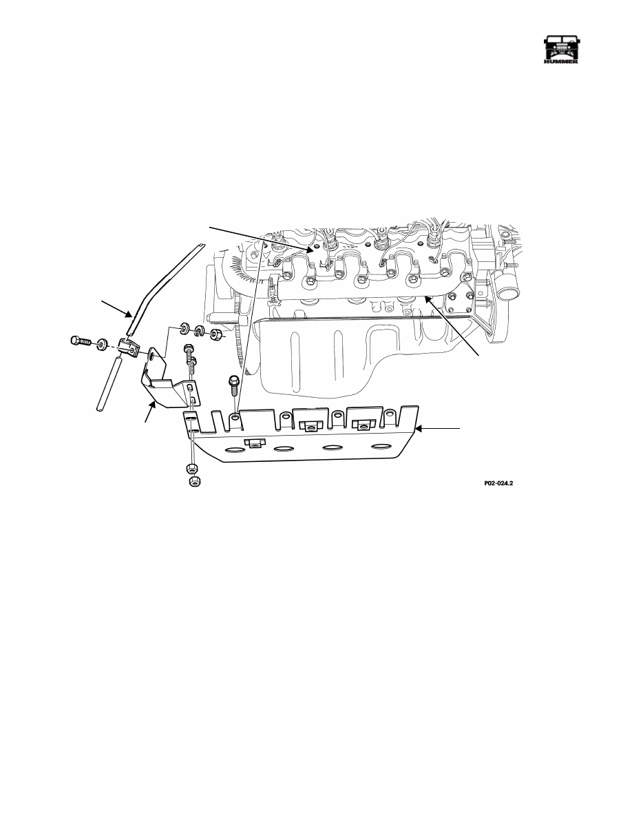
Right Exhaust Manifold Rear Heat Shield
Replacement
1.
Remove console and engine access cover.
2.
Detach rear heat shield from transmission fill tube clamp
(Figure 2-39).
3.
Remove rear heat shield.
4.
Install rear heat shield.
5.
Attach rear heat shield to transmission fill tube clamp.
6.
Install engine access cover and console.
Figure 2-39: Right Rear Heat Shield
CYLINDER HEAD
HEAT SHIELD
TRANSMISSION
EXHAUST MANIFOLD
REAR
HEAT
SHIELD
FILL TUBE
Нет комментариевНе стесняйтесь поделиться с нами вашим ценным мнением.
Текст