Hummer H1 (2002+). Manual — part 19

____________________________________________________________________
Engine 2-37
¨
05745159
CYLINDER HEAD AND GASKET SERVICE
Cylinder Head (Left Side)
Removal
1.
Remove hood with aid of helper as follows:
¥
Disconnect hood harness
¥
Remove harness clips at driver side frame rail bracket
¥
Remove bolts that attach prop rod bracket to driver
side frame bracket
¥
Remove hood hinge pins
¥
Lift and remove hood
2.
Remove front console and engine cover.
3.
Drain radiator and disconnect batteries.
4.
Disconnect and cover fluid cooler lines at transmission
and power steering coolers.
5.
Remove driver side splash shield.
6.
Remove serpentine belt.
7.
Remove air intake hose and air horn.
8.
Remove A/C compressor, power steering pump, and
mounting bracket as assembly. Position A/C compressor
to side to allow access to rocker cover and cylinder head.
9.
Remove oil dipstick tube, water crossover, thermostat
housing, coolant hoses, and radiator upper hose inlet tube.
10. Disconnect or remove (Figure 2-40):
¥ Heater water valve bracket
¥ Wire harness clips and brackets
¥ Ground wires/cables at rear of cylinder head
¥ Temperature sender wire
¥ Fuel pump
¥ Glow plugs
11. Remove fuel injector line clamps. Retain clamps and
attaching washers and nuts.
Figure 2-40: Ground Connections at Rear of
Cylinder Head
12. Remove intake manifold and gaskets. Note attaching stud
and bolt locations for reinstallation reference.
13. Disconnect driver side fuel injector lines at pump and
injectors and remove lines. Cover injectors with duct tape
to prevent dirt entry.
14. Remove bolts/nuts attaching crossover pipe to exhaust
manifold.
15. Remove rocker arm cover. Tap cover with rubber mallet to
loosen. Do not pry on cover to remove.
16. Remove rocker arm shaft bolts and retainers. Remove arm
and shaft assemblies individually. Note original position
for assembly reference.
17. Remove pushrods. Note position of rods for installation
reference as they must be installed in original position.
18. Remove cylinder head bolts. Discard bolts as they are not
reusable.
19. Remove cylinder head (Figure 2-41) with aid of helper, or
use chain hoist, portable hoist, or similar device to lift and
remove cylinder head.
Figure 2-41: Cylinder Head and Gasket
Removal/Installation
20. Remove cylinder head gasket. Discard gasket; it is not
reusable.
21. Refer to overhaul section if head, valves, valve seats,
springs, or seals require service. Check for warpage. If
head was only removed to replace blown gasket, proceed
to installation procedure.
22. Cover cylinder bores and lifter valleys with shop towels.
CYLINDER HEAD
DOWEL
COOLANT
TEMPERATURE
SENDER
DOWEL
2-38
Engine
_____________________________________________________________________
¨
Cylinder Head (Left Side)
Installation
1.
Clean gasket surface of cylinder block with scraper if nec-
essary. Then remove protective covering from cylinder and
lifter valleys.
2.
Wipe cylinder block surface clean with solvent and cloth.
3.
Position new head gasket on cylinder block. Be sure
gasket is aligned on cylinder block dowels.
CAUTION: Install the new gasket dry. Do not use any type of
sealer on the gasket. Sealer can prevent proper seating and re-
sult in coolant leaks.
4.
Install cylinder head with aid of helper or with hoist. Be
sure head is properly seated on cylinder block dowels.
5.
Install and tighten new cylinder head bolts as follows:
a.
Apply light coat of Teflon Pipe Sealant (PST) to
threads and under heads of new bolts.
b.
Install and tighten bolts to initial torque of 20 lb-ft (27
N¥m). Follow tightening sequence (Figure 2-42).
c.
Tighten bolts to 50 lb-ft (68 N¥m) torque evenly and
in sequence shown (Figure 2-42).
d.
Final-tighten bolts an additional 90¡ (1/4-turn).
6.
Install pushrods. Verify that they are in same sequence as
when removed. Also be sure heat treated (copper color)
end is toward rocker arm.
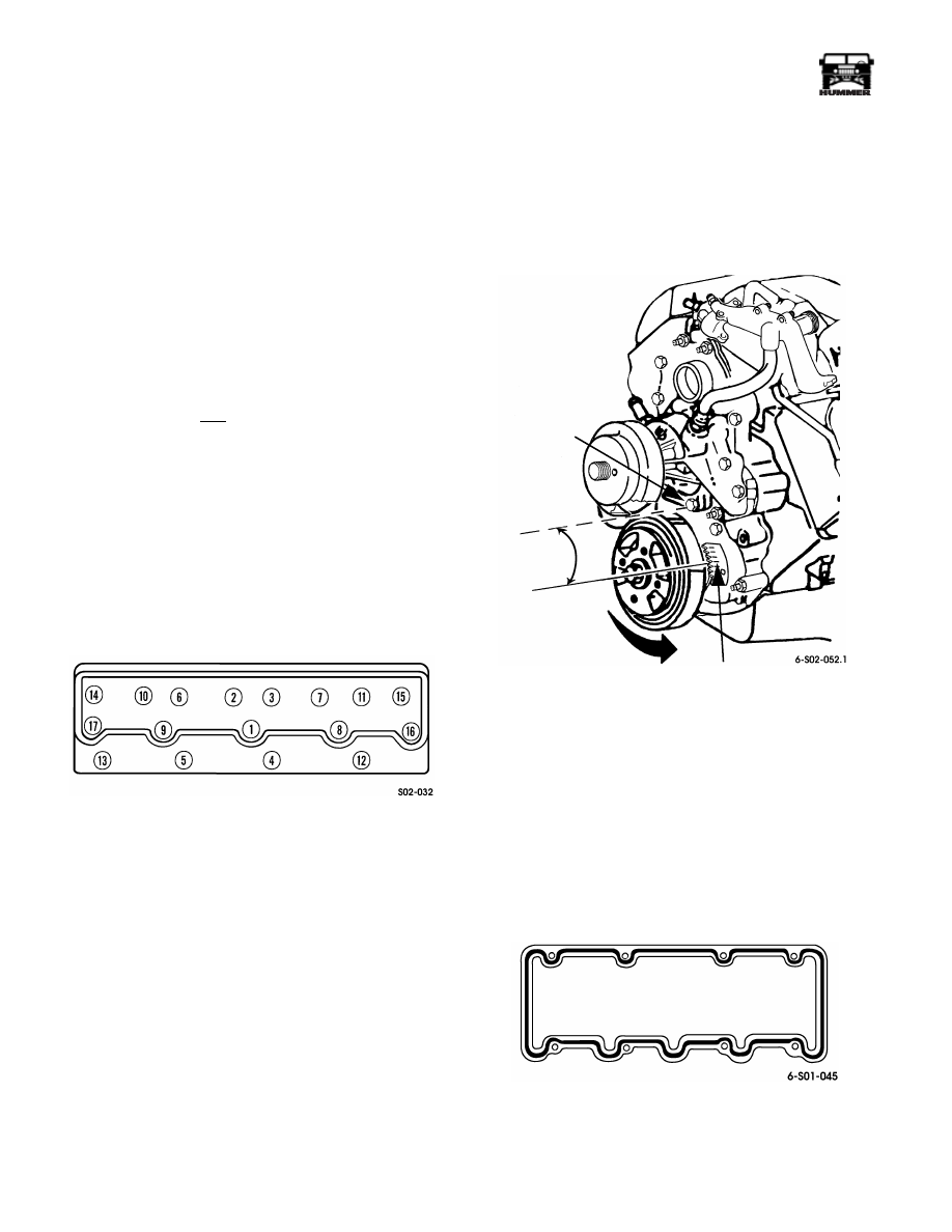
Figure 2-42: Cylinder Head Bolt Tightening
Sequence
7.
Index crankshaft and pistons for rocker arm and shaft
installation as follows:
a.
Position breaker bar and socket on crankshaft damper
bolt. Do not use starter motor to rotate crankshaft. Use
socket and wrench on damper bolt only.
b.
Rotate crankshaft counterclockwise and align mark
on torsional damper with ÒOÓ (TDC) mark on front
cover timing tab.
c.
Index crankshaft by rotating it counterclockwise an
additional 3-1/2 inches (89 mm). At this point, mark
on damper will be roughly aligned with first lower
water pump bolt (Figure 2-43).
8.
Install rocker arm and shaft assemblies. Be sure pushrods
are properly seated in lifter and rocker arms. Do this
before tightening shaft retainer bolts. Install shaft retainers
and bolts. Tighten bolts evenly to 41 lb-ft (56 N¥m)
torque.
CAUTION: Stop tightening the shaft bolts if they become hard
to turn before fully seated.
Figure 2-43: Crankshaft Indexing Position
9.
Clean cylinder head and rocker cover sealing surfaces
thoroughly. Then finish-clean with brake or contact
cleaner and shop towels to remove cleaning residue. This
is necessary to ensure proper adhesion of sealer.
10. Apply sealer to rocker arm cover (Figure 2-44). Make
sealer bead 3/16 inch wide by 1/16 inch thick. Use RTV-
type silicone, adhesive-sealer such as Loctite 592, or
Permatex High Temp, Ultra Copper, or Ultra Blue. Allow
sealer to cure slightly (skin over) before installing cover.
Figure 2-44: Applying Sealer to Rocker Arm Cover
11. Align and install rocker cover. Tighten cover bolts to 16
lb-ft (22 N¥m) torque.
WATER PUMP
FIRST LOWER
BOLT
3 1/2 IN.
(89 MM)
O (TDC) MARK
ON TIMING TAB
____________________________________________________________________
Engine 2-39
¨
05745159
12. Install fuel injector lines. Tighten line fittings at pump and
injector to 19 lb-ft (26 N¥m) torque.
13. Install intake manifold and gaskets. Tighten manifold
studs/bolts to 31 lb-ft (42 N¥m) torque. Also install
turbocharger, if equipped.
14. Install engine oil dipstick tube, if removed, and connect
tube to rocker cover bracket.
15. Install water crossover and thermostat housing. Use new
gaskets on crossover and tighten attaching bolts to 25-
37 lb-ft (34-50 N¥m) torque.
16. Install fuel injector line clamps, washers, and nuts.
Tighten nuts to 26 lb-ft (35 N¥m) torque.
17. Install or connect:
¥
glow plugs
¥
fuel pump
¥
temperature sender wire (at head)
¥
ground wires/cables (at rear of head)
¥
wire harness clips and brackets
¥
water valve and bracket
18. Install A/C compressor, power steering pump, and pump
mounting bracket.
19. Install serpentine belt.
20. Install air intake hose and air horn. Be sure gasket is seated
on manifold before tightening air horn bolts.
21. Connect radiator hoses, inlet tube, A/C lines, and fluid
cooler lines.
22. Refill engine cooling system.
23. Connect batteries.
24. Start and run engine. Bleed injectors by loosening line
fittings just enough to purge air. Then tighten fittings and
stop engine.
25. Check and top off engine coolant, engine oil, and
transmission fluid as required.
26. Clear codes and test drive.
Cylinder Head (Right Side)
Removal
1.
Remove front console and engine cover.
2.
Drain radiator and disconnect batteries.
3.
Remove batteries and battery tray.
4.
Remove passenger side splash shield.
5.
Remove air cleaner, inlet hose, and air horn.
6.
Remove surge tank and water valve and hoses.
7.
Remove crossover and thermostat housing, inlet tube, and
radiator upper hoses as assembly.
8.
Remove serpentine belt.
9.
Disconnect and remove alternator, brackets, idler pulley,
and tensioner.
10. Disconnect or remove:
¥
Glow plug relay and bracket
¥
Engine wire harness clips and ground wires
¥
Passenger side glow plugs and glow plug relay
11. Remove fuel injector line clamps, washers, nuts
12. Remove intake manifold and gaskets. Note attaching stud
and bolt locations for installation reference.
13. Disconnect passenger side fuel injector lines at pump and
injectors, and remove lines. Cover injectors with duct tape
to prevent dirt entry.
14. Remove heat shield and guard. Then remove bolts/nuts
attaching crossover pipe to exhaust manifold.
15. Remove rocker arm cover. Tap cover with rubber mallet to
loosen. Do not pry on cover to remove.
16. Remove rocker arm shaft bolts and retainers. Remove arm
and shaft assemblies individually. Note original position
for assembly reference.
17. Remove pushrods. Note position or rods for installation
reference as they must be installed in original position.
18. Remove cylinder head bolts. Discard bolts as they are not
reusable.
19. Remove cylinder head with aid of helper. Or use chain
hoist, portable hoist, or similar device to lift and remove
cylinder head.
20. Remove cylinder head gasket. Discard gasket; it is not
reusable.
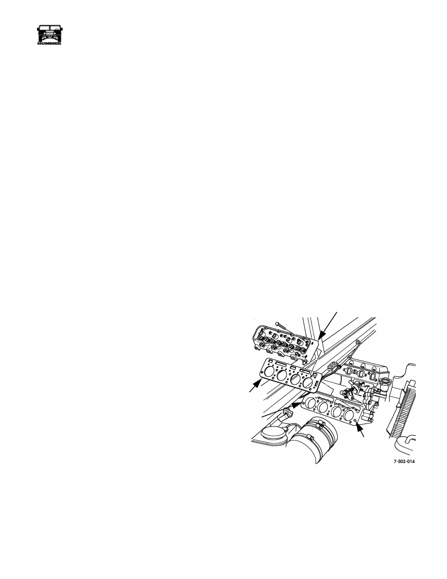
Figure 2-45: Right Side Cylinder Head Removal/
Installation
21. Refer to cylinder head cleaning and inspection information
if head, valves, valve seats, springs, or seals require
service. Check for warpage. If head was only removed to
replace blown gasket, proceed to installation procedure.
22. Cover cylinder bores and lifter valleys with shop towels.
GASKET
CYLINDER HEAD
DOWEL
DOWEL

2-40
Engine
_____________________________________________________________________
¨
Cylinder Head (Right Side)
Installation
1.
Clean gasket surface of cylinder block with scraper if nec-
essary. Scuff sand surface with 180 grit emery or paper to
provide better surface for gasket seating. Then remove
protective covering from cylinders and lifter valleys.
2.
Wipe cylinder block surface clean with solvent and cloth.
3.
Position new head gasket on cylinder block. Be sure
gasket is aligned on cylinder block dowels.
CAUTION: Install the new gasket dry. Do not use any type of
sealer on the gasket. Sealer can prevent proper seating and re-
sult in coolant leaks.
4.
Install cylinder head with aid of helper or with hoist.
5.
Install and tighten new cylinder head bolts as follows:
a.
Apply light coat of sealer, such as Loctite Pipe Seal-
ant w/Teflon, to thread and under heads of new bolts.
b.
Install and tighten bolts to initial torque 20 lb-ft (27
N¥m). Follow tightening sequence shown
(Figure 2-42).
c.
Tighten bolts to 50 lb-ft (68 N¥m) torque evenly and
in sequence shown (Figure 2-42).
d.
Final-tighten bolts an additional 90¡ (1/4-turn).
6.
Install pushrods. Verify that they are in same sequence as
when removed. Also be sure heat treated end is toward
rocker arm.
7.
Index crankshaft and pistons for rocker arm and shaft
installation as follows:
a.
Position breaker bar and socket on crankshaft damper
bolt. Do not use starter motor to rotate crankshaft. Use
hand tools only.
b.
Rotate crankshaft counterclockwise and align mark
on torsional damper with ÒOÓ (TDC) mark on front
cover timing tab (Figure 2-43).
c.
Index crankshaft by rotating it counterclockwise an
additional 3-1/2 inches (89 mm). At this point, mark
on damper will be roughly aligned with first lower
water pump bolt (Figure 2-43).
8.
Install rocker arm and shaft assemblies. Be sure pushrods
are properly seated in lifters and rocker arms. Do this
before tightening shaft retainer bolts. Install shaft retainers
and bolts. Tighten bolts evenly to 41 lb-ft (56 N¥m)
torque.
CAUTION: Stop tightening the shaft bolts if they become hard
to turn before they are fully seated. Check for misalignment or
unseated push rods.
9.
Clean cylinder head and rocker cover sealing surfaces
thoroughly. Then finish-clean with brake or contact
cleaner and shop towels to remove residue. This is
necessary to ensure proper seal adhesion.
10. Apply sealer to rocker arm cover. Make sealer bead 3/16
inch wide by 1/16 inch thick. Use RTV-type silicone,
adhesive-sealer such as Loctite 592, or Permatex High
Temp, Ultra Copper, or Ultra Blue. Allow sealer to cure
slightly (skin over) before installing cover.
11. Align and install rocker cover. Tighten cover bolts to 16
lb-ft (22 N¥m) torque.
12. Install fuel injector lines. Tighten line fittings at pump and
injector to 19 lb-ft (26 N¥m) torque.
13. Install intake manifold and gaskets. Tighten manifold
studs/bolts to 31 lb-ft (42 N¥m) torque.
14. Install water crossover and thermostat housing. Use new
gaskets on crossover and tighten attaching bolts to 25-37
lb-ft (34-50 N¥m) torque.
15. Install or connect:
¥
Glow plugs and glow plug relay and bracket
¥
Engine harness wires, clips, and brackets
¥
Water valve bracket
16. Install and attach transmission fill tube.
17. Install heat shield and shield guard. Tighten heat shield
bolts to 25 lb-ft (34 N¥m) torque.
18. Install support bracket on rear of alternator and mounting
bracket. Then install alternator, bracket, and tensioner as
assembly. Connect alternator wires afterward.
19. Install vacuum pump.
20. Install serpentine belt.
21. Install surge tank.
22. Install air cleaner, air horn, inlet hose, and shield.
23. Assemble radiator upper hoses and tube and connect to
thermostat housing.
NOTE: Check condition of the O-rings on the A/C and oil
cooler fittings. Replace the O-rings if cut, worn, or distorted.
24. Connect radiator upper hose, heater hoses, and surge tank
hoses.
25. Refill cooling system.
26. Install passenger side splash shield. Then install battery
tray and horns (if removed).
27. Install and connect batteries.
28. Top off engine oil and transmission fluid as needed.
29. Start and run engine. Bleed injectors by loosening line
fittings just enough to purge any air. Then tighten fittings
and stop engine.
30. Top off engine coolant, oil, and transmission fluid as
required.
31. Clear codes and test drive.
Нет комментариевНе стесняйтесь поделиться с нами вашим ценным мнением.
Текст