Hummer H1 (2002+). Manual — part 113
____________________________________________________________
Brake System 7-11
®
05745159
Installation
1.
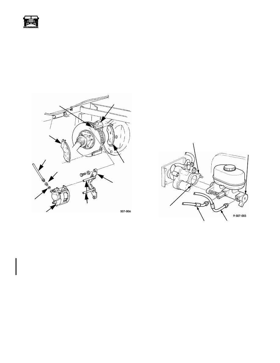
Install a washer and coupling to caliper (Figure 7-6).
WARNING: Ensure brake pads are installed with lin-
ings facing rotor. Failure to do this will cause poor per-
formance and damage to equipment and may result in
injury.
2.
Position brake pads on adapter (Figure 7-7).
Figure 7-7: Service Brake Components
3.
Apply a non-hardening thread-locking compound to
threads of caliper guide pins and install pins into yoke (if
removed during cleaning and inspection). Tighten caliper
guide pins to 30 lb-ft (41 N•m).
4.
Lubricate caliper guide pins, sleeves and adapter slides
with Permatex
®
Ultra Disc Brake Caliper Lube prior to
installation.
5.
Position caliper onto yoke.
NOTE:
When installing calipers, use a suitable tool to bottom
out piston in caliper if needed.
6.
Apply thread-locking compound to tapped holes of
adapter. Using crowfoot, secure yoke and caliper to
adapter with two washers and capscrews. Tighten two
capscrews to 40 lb-ft (54 N•m).
7.
Connect brake line to coupling.
8.
Bleed brake system.
MASTER CYLINDER REPLACEMENT
Removal
CAUTION:
Cover or plug all open connections immediately
after disconnecting to prevent contamination
NOTE:
Have drainage container ready to catch brake fluid.
1.
Disconnect front and rear brake lines from master cylinder
(Figure 7-8).
CAUTION:
Do not apply excessive pressure or force on mas-
ter cylinder.
2.
Remove two locknuts and master cylinder from hydro-
boost. Discard locknuts (Figure 7-8).
Installation
1.
Bench-bleed master cylinder.
Figure 7-8: Master Cylinder
2.
Install master cylinder to hydro-boost with two locknuts.
Tighten locknuts to 22 lb-ft (30 N•m) (Figure 7-8).
3.
Install front and rear brake lines to master cylinder.
Position front and rear brake lines with a minimum of 1/2"
clearance to the hydro-boost accumulator and the right
rear modulator output line. Clearance between the front
and rear lines is also 1/2" minimum.
ADAPTER
BRAKE PAD
YOKE
CALIPER
CALIPER
COUPLING
BRAKE PAD
TAPPED HOLE
GUIDE PINS
BRAKE
LINE/HOSE
COPPER
WASHER
HYDRO-BOOST
MASTER
CYLINDER
REAR
BRAKE
LINE
FRONT
BRAKE
LINE
RIGHT MASTER
CYLINDER
MOUNTING STUD
4-1-00
7-12
Brake System
_____________________________________________________________
®
MASTER CYLINDER BLEEDING
NOTE:
Master cylinder must be filled and kept at least half
full during bleeding operation (Figure 7-9).
1.
Depress brake pedal slowly and hold. Loosen front brake
line to purge air from the front section of the reservoir.
2.
Tighten front brake line and release brake pedal.
3.
Repeat steps 1 and 2 until front reservoir is purged of air.
4.
Repeat steps 1 through 3 for rear reservoir with rear brake
line.
5.
Bleed brake system.
MASTER CYLINDER BENCH BLEEDING
NOTE:
Master cylinder must be filled and kept at least half
full during bleeding operation. Perform this procedure prior to
installing master cylinder on vehicle.
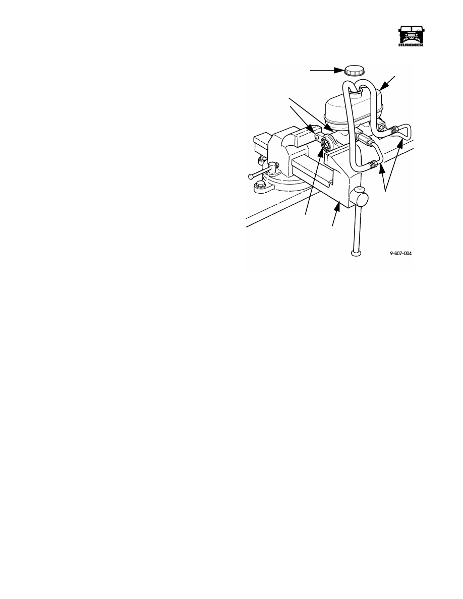
1.
Secure master cylinder flange in vise.
2.
Remove cover and fill reservoir with DOT 3 brake fluid.
3.
Screw threaded end of bleeder hose into brake line port on
master cylinder and insert opposite end into reservoir.
Repeat step for other bleeder hose (Figure 7-9).
4.
Slowly push piston into master cylinder. Do not release
piston. Air will be forced into hoses. Repeat as needed
until no bubbles noted from lines. Lines must stay in fluid
until installed.
5.
Refill reservoir with DOT 3 brake fluid and repeat step 4
until no air bubbles remain in brake fluid.
6.
Remove bleeder hoses from brake line ports on master
cylinder.
7.
Install cap on master cylinder and remove from vise.
8.
Install master cylinder.
9.
Bleed brake system.
Figure 7-9: Bench Bleeding Master Cylinder
CAP
BLEEDER
VISE
PISTON
FLANGE
MASTER CYLINDER
HOSES
RESERVOIR
____________________________________________________________
Brake System 7-13
®
05745159
HYDRO-BOOST REPLACEMENT
Removal
1.
Remove two nuts securing splash shield mount bracket to
hydro-boost/master cylinder assembly.
2.
Remove nut securing mount bracket to splash shield and
remove mount bracket.
3.
Remove two nuts securing the master cylinder to the
hydro-boost and pull the master cylinder out and to one
side.
4.
Disconnect two high pressure lines and one return line
from hydro-boost (Figure 7-10).
5.
Remove cotter pin, washer, and pushrod from brake pedal
bellcrank. Remove spring washer from brake pedal
bellcrank and discard cotter pin and spring washer.
6.
Remove four nuts, lockwashers, washers, gasket, and
hydro-boost from cowl. Discard lockwashers.
Installation
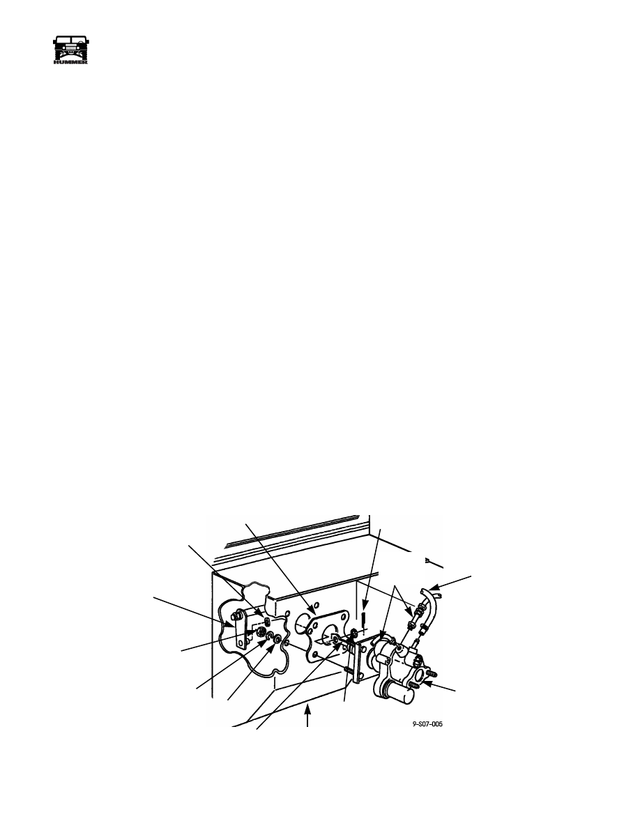
1.
Install gasket and hydro-boost on cowl with four washers,
lockwashers, and nuts. Do not tighten nuts. (Figure 7-10).
2.
Install spring washer on brake pedal bellcrank. Connect
hydro-boost pushrod to brake pedal bellcrank. Install
washer and cotter pin.
3.
Tighten nuts to 21 lb-ft (28 N•m).
4.
Connect two high pressure lines and one return line to
hydro-boost.
5.
Install master cylinder and splash shield mount bracket.
6.
Bleed hydro-boost system.
BLEEDING THE HYDRO-BOOST SYSTEM
Whenever the booster is removed and installed, the steering
system should be bled.
1.
Fill the power steering pump reservoir to the proper level
and let the fluid remain undisturbed for at least two min-
utes.
2.
Start the engine and run momentarily. Add fluid if
necessary.
3.
Repeat steps 1 and 2 until the fluid level remains constant
after running the engine.
4.
Turn off the engine.
5.
Raise the front of the vehicle so the wheels are off the
ground. Support the vehicle with suitable safety stands.
6.
Turn the wheels from stop to stop. Add fluid if necessary.
7.
Lower the vehicle from the safety stands.
8.
Start the engine and depress the brake pedal several times
while rotating the steering wheel from stop to stop.
9.
Turn the engine off and pump the brake pedal 4 to 5 times.
CAUTION: The HUMMER is equipped with DOT 3 brake
fluid. Do not mix with other brake fluids. Failure to use the
proper brake fluid will damage brake system.
10. Check the brake fluid level. Add fluid if necessary.
11. If the fluid is extremely foamy, allow the vehicle to stand a
few minutes with the engine on. Then repeat steps 7, 8,
and 9.
12. Check for the presence of air in the oil. Air in the oil will
give the fluid a milky appearance. Air in the system will
also cause the fluid level in the pump to rise when the
engine is turned off.
Figure 7-10: Hydro-boost Replacement Procedure
SPRING WASHER
BRAKE
PEDAL
BELLCRANK
COWL
PUSHROD
HYDRO-BOOST
RETURN LINE
GASKET
HIGH
PRESSURE
LINES
FLATWASHER
PIN
NUTS
LOCKWASHER
WASHER
7-14
Brake System
_____________________________________________________________
®
BRAKE LINE REPLACEMENT
Metal brake lines should be inspected for leaks or deterioration
every time the vehicle is being serviced.
WARNING: Batteries must be disconnected when the
brake hydraulic system is being serviced and bled. If the
ABS motor pump runs when air is in the hydraulic sys-
tem, air can get trapped behind the valves in the modu-
lator causing a spongy brake pedal.
NOTE:
After servicing the brake system, bleed the brakes and
refill as necessary.
Front Brake Line Replacement
NOTE:
The procedure is the same for the right and left front
brake lines.
1.
Disconnect the brake line from the caliper.
2.
Disconnect the brake line from the the ABS modulator
assembly.
3.
Remove the capscrew and clamp securing the brake line to
the crossmember, and remove the brake line (Figure 7-11).
4.
Reverse the removal procedure for installation and bleed
the brake hydraulic system.
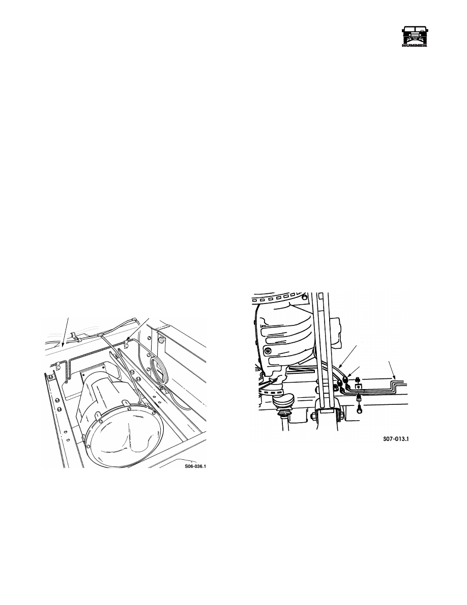
Figure 7-11: Front Brake Line Replacement
Intermediate Brake Line Replacement
NOTE:
The procedure is the same for the right and left inter-
mediate brake lines.
1.
Disconnect the intermediate brake line from the ABS mod-
ulator assembly.
2.
Disconnect the intermediate brake line from the rear brake
line at the union located forward of the forward-rear
crossmember.
3.
Remove the capscrews and clamps securing the
intermediate brake line to the frame rail and remove the
brake line from the vehicle.
4.
Reverse the removal procedure for installation and bleed
the brake hydraulic system.
Rear Brake Line Replacement
Removal
1.
Disconnect the rear brake line from the caliper.
2.
Disconnect rear brake line from the intermediate brake
line at the union located forward of the forward-rear
crossmember (Figure 7-12).
Figure 7-12: Rear Brake Line Replacement
3.
Remove the capscrew and clamp securing the rear brake
line to the forward-rear crossmember and remove the
brake line from the vehicle.
4.
Reverse the removal procedure for installation and bleed
the brake hydraulic system.
CLAMP
CROSSMEMBER
UNION
INTERMEDIATE
LINE
REAR
LINE
Нет комментариевНе стесняйтесь поделиться с нами вашим ценным мнением.
Текст