Hummer H1 (2002+). Manual — part 114
____________________________________________________________
Brake System 7-15
®
05745159
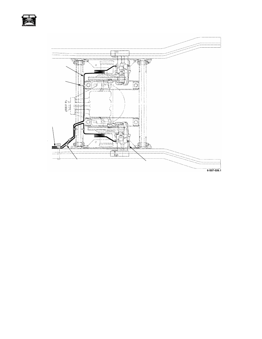
Figure 7-13: Rear Brake Component Location
METAL
BRAKE
LINES
CALIPER
FROM
ABS/TT4
MODULATOR
LINE
MOUNTIG
CLIP
UNION
7-16
Brake System
_____________________________________________________________
®
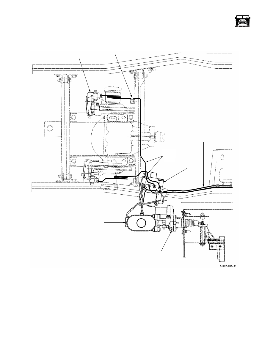
Figure 7-14: Front Brake Component Location
CALIPER
MASTER CYLINDER
HYDROBOOST
METAL
BRAKE
LINES
LINE
MOUNTING
CLIP
METAL LINES
TO REAR CALIPERS
ABS
MODULATOR

____________________________________________________________
Brake System 7-17
®
05745159
SERVICE BRAKE PEDAL REPLACEMENT
Removal
1.
Disconnect the stoplight switch (Figure 7-15).
2.
Remove pushnut and disconnect stoplight switch rod (if so
equipped) from brake pedal assembly. Discard pushnut.
(Figure 7-15).
3.
Disconnect return spring from brake pedal assembly.
4.
Remove cotter pin and washer securing hydro-boost
pushrod to brake pedal bellcrank, and disconnect hydro-
boost pushrod from brake pedal bellcrank. Remove spring
washer. Discard cotter pin and spring washer.
5.
Remove nut, two washers, pivot pin, and brake pedal
assembly from bracket.
6.
Remove two bushings from brake pedal assembly. Discard
two bushings.
Installation
1.
Apply silicone grease to inside of two bushings. Install two
bushings in brake pedal assembly.
2.
Install brake pedal assembly on bracket with pivot pin, two
washers, and nut. Using adapter and crowfoot, tighten nut to
60 lb-ft (81 N•m).
3.
Install spring washer on brake pedal bellcrank. Connect
hydro-boost pushrod to brake pedal bellcrank with washer
and cotter pin.
4.
Connect return spring to brake pedal assembly.
5.
Use the pushnut to install the stoplight switch rod (if so
equipped) to brake pedal assembly.
6.
Connect the stoplight switch.
7.
Operate vehicle and check brakes for proper operation.
8.
Check brake lights for proper operation.
Figure 7-15: Service Brake Pedal Components
SERVICE BRAKE ROTOR REPLACEMENT
Removal
1.
Remove service brake caliper.
2.
Remove six capscrews, lockwashers, halfshaft, and rotor
from output flange. Discard lockwashers (Figure 7-17).
Installation
1.
Apply thread-locking compound to threads of capscrews.
2.
Install rotor on output flange.
3.
Secure halfshaft and rotor to output flange with twelve
inclined cam lockwashers and capscrews with preapplied
threadlocker. Tighten capscrews to 57 lb-ft (77 N•m).
4.
Install service brake caliper.
Figure 7-16: Hydro-Boost And Master Cylinder
Mounting
Figure 7-17: Service Brake Rotor
PIVOT PIN
STOPLIGHT
BRACKET
BUSHING
BRAKE PEDAL
BRAKE PEDAL
HYDRO-BOOST
RETURN SPRING
PUSHROD
BELLCRANK
ASSEMBLY
STRIKER
SPRING
SWITCH
WASHER
FRONT BRAKE LINE
HYDRO-
MASTER
REAR BRAKE LINE
BOOST
CYLINDER
HALFSHAFT
ROTOR
OUTPUT FLANGE
7-18
Brake System
_____________________________________________________________
®
REAR DUAL SERVICE/PARKING BRAKE PAD
REPLACEMENT
Removal
1.
Put transmission in PARK, chock wheels, and release
parking brake.
2.
Remove cotter pin, washer, and clevis pin securing
parking brake cable to lever. Discard cotter pin
(Figure 7-18).
3.
Remove clip securing parking brake cable to caliper cable
bracket and disconnect cable from caliper cable bracket.
Discard clip.
CAUTION: Caliper must be supported during removal to pre-
vent damage to brake line.
4.
Remove two capscrews and washers securing yoke and
caliper to adapter, and pull yoke and caliper away from
rotor (Figure 7-19).
NOTE:
Note positioning of brake pad surfaces for installation.
5.
Remove two brake pads from adapter and rotor.
Cleaning and Inspection
NOTE:
Clean all components, examine for wear or damage,
and replace if necessary.
1.
Clean mating surfaces of caliper and adapter and lightly
lubricate adapter slides with brake component lubricant
(Figure 7-19).
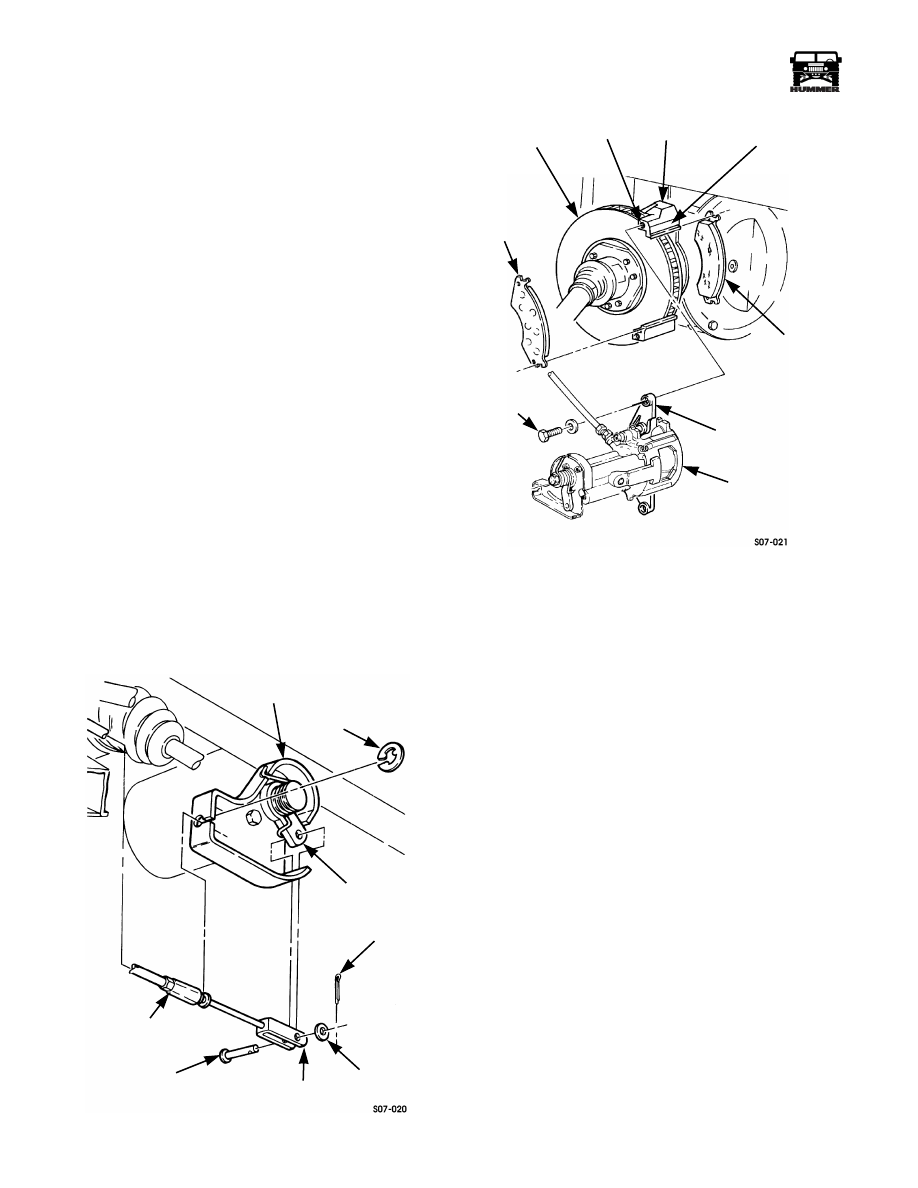
Figure 7-18: Rear Dual Brake Components
Figure 7-19: Rear Dual Brake Pad and Rotor
2.
Inspect caliper and caliper piston face for pitting or
damage (Figure 7-20).
3.
Inspect piston dust boot and bushings for tears or
deterioration.
4.
Inspect caliper cable bracket for looseness, damage, and
rotation.
5.
Thoroughly clean and inspect rotor for heat checks,
discoloration, pitting, or scoring (Figure 7-19).
CAUTION: Ensure that grease and oil are not in contact with
rotor and/or brake pad friction surface. Failure to do so will
result in damage to equipment and poor performance.
NOTE:
Replace brake pads in sets only. If operation in wet
and muddy conditions is expected, replace brake pads if brake
lining thickness is less than 1/8 in. (3.2 mm).
6.
Inspect brake pads for glazing, oil saturation, or wear. If
glazed, oil saturated, or if brake lining thickness is less
than 1/8 in. (3.2 mm), replace both pads and pads on
opposite caliper.
CALIPER CABLE
CLIP
PARKING BRAKE
CABLE
CLEVIS PIN
PARKING BRAKE
LEVER
CLEVIS
BRACKET
COTTER
PIN
WASHER
ADAPTER
BRAKE PAD
ADAPTER SLIDE
YOKE
CALIPER
BRAKE PAD
ROTOR
TAPPED
HOLE
CAP
SCREW
Нет комментариевНе стесняйтесь поделиться с нами вашим ценным мнением.
Текст