Hummer H1 (2002+). Manual — part 24
____________________________________________________________________
Engine 2-57
®
05745159
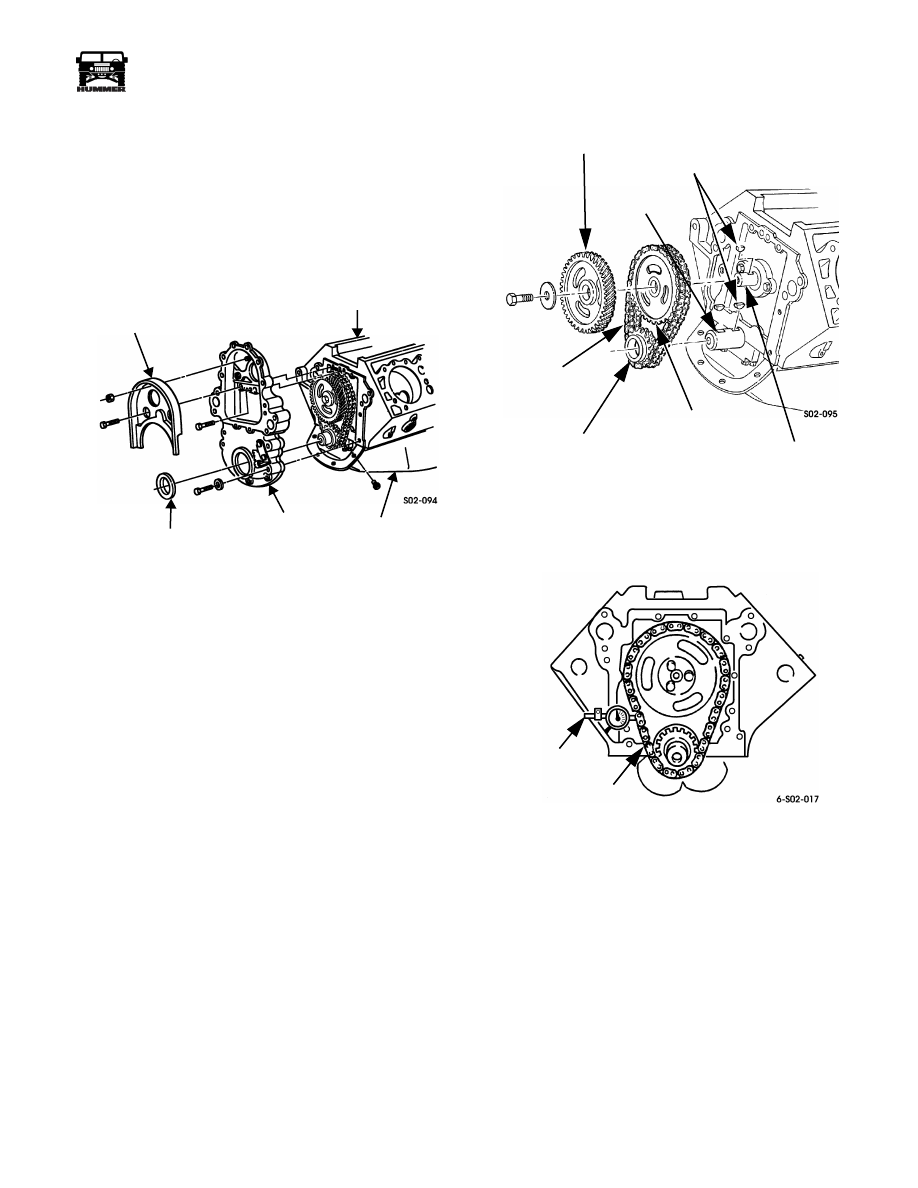
Front Cover Removal
1.
Remove baffle from front cover (Figure 2-87).
2.
Remove bolts attaching front cover to oil pan.
3.
Remove bolts attaching front cover to engine block.
4.
Remove front cover. Use mallet to loosen cover. Do not
pry cover loose.
5.
Remove oil seal from cover.
Figure 2-87: Front Cover and Baffle Removal
Timing Chain, Drive Sprockets, Drive Gear
Removal
1.
Measure timing chain deflection. Deflection must not exceed
0.810 in. (21 mm). Use dial indicator J–8001 (Figure 2-89).
2.
Measure camshaft end play. End play should not exceed
0.012 in. (0.3 mm). If end play exceeds 0.012 in. (0.3
mm), camshaft sprocket, thrust plate, or spacer is worn
and will have to be replaced.
3.
Remove injection pump drive gear bolt and remove drive
gear from camshaft.
4.
Remove crankshaft sprocket, camshaft sprocket, and
timing chain as assembly (Figure 2-88).
Figure 2-88: Timing Chain, Drive Sprocket,
Drive Gear Removal
5.
Remove drive keys from camshaft and crankshaft.
Figure 2-89: Measuring Timing Chain Deflection
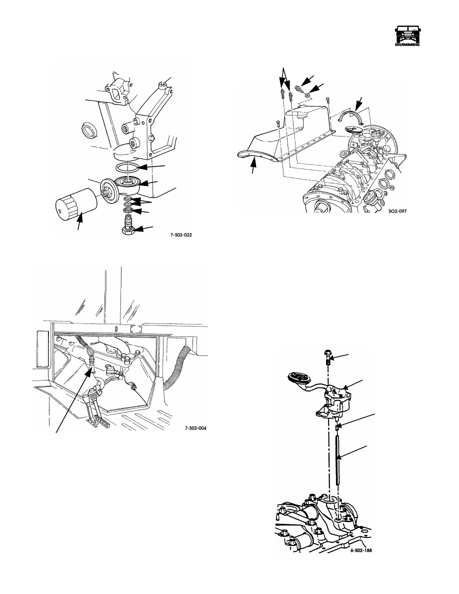
Oil Filter, Adapter, and Oil Pressure Sending
Unit Removal
1.
Remove oil filter from adapter (Figure 2-89). Discard oil
filter.
2.
Remove adapter bolt, washer, seals and adapter.
3.
Unplug electrical connector and remove oil pressure
sending unit from engine valley (Figure 2-91).
COVER OIL SEAL
BAFFLE
FRONT
CYLINDER BLOCK
OIL PAN
COVER
DRIVE KEYS
CRANKSHAFT
TIMING CHAIN
CRANKSHAFT
CAMSHAFT SPROCKET
DRIVE GEAR
CAMSHAFT
INJECTION PUMP
SPROCKET
CHAIN
DIAL
INDICATOR
J8001
2-58
Engine
_____________________________________________________________________
®
Figure 2-90: Oil Filter and Adapter Removal
Figure 2-91: Oil Pressure Sending Unit Location
Oil Pan Removal
1.
Drain oil from pan if not previously done.
2.
Remove pan bolts.
3.
Tap pan with rubber mallet to loosen. Then remove pan.
4.
Remove pan rear seal (Figure 2-92). Discard seal.
Figure 2-92: Oil Pan Removal
Oil Pump and Drive Removal
1.
Remove nut from pump mounting stud (Figure 2-93).
2.
Loosen bracket clamp screw and rotate bracket off
mounting stud.
3.
Remove pump mounting stud.
4.
Lift and remove pump and pump shaft.
5.
Remove oil pump drive clamp.
6.
Lift and remove oil pump drive from block (Figure 2-94).
7.
Remove and discard pump drive gasket.
Figure 2-93: Oil Pump Removal/Installation
SEAL
ADAPTER
SEALS
WASHER
OIL FILTER
BOLT
OIL PRESSURE
SENDING UNIT
STUDS
DRAINPLUG
GASKET
OIL PAN
SEAL
OIL PUMP
MOUNTING
BOLT
PUMP DRIVE
SHAFT
SHAFT
RETAINER
____________________________________________________________________
Engine 2-59
®
05745159
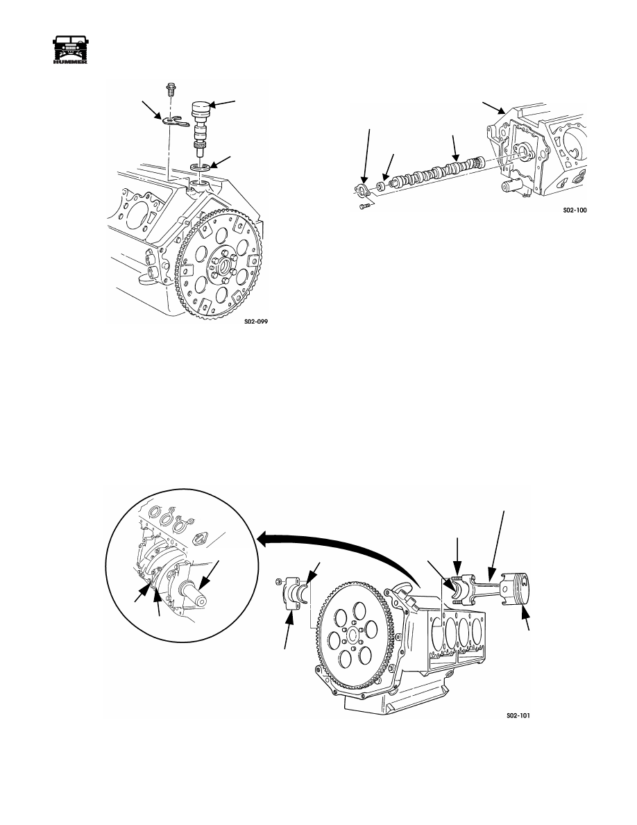
Figure 2-94: Oil Pump Drive Removal
Camshaft Removal
1.
Remove thrust plate and spacer (Figure 2-95).
CAUTION: Support camshaft during removal to avoid damag-
ing bearings.
2.
Remove camshaft from cylinder block.
Figure 2-95: Camshaft Removal
Piston and Connecting Rod Removal
1.
Remove ridge at top of each cylinder bore with ridge
reamer J–24270. Remove shavings - chips afterward.
2.
Paint mark pistons for assembly reference.
3.
Mark connecting rod caps with punch, if caps do not have
factory marks.
4.
Remove each piston - connecting rod assembly as follows
(Figure 2-96):
a.
Remove number one piston connecting rod cap nuts.
b.
Remove rod cap and bearing half. Retain bearing for
select fit reference.
c.
Slide lengths of appropriate size rubber hose over
Figure 2-96: Piston and Connecting Rod Removal
CLAMP
OIL PUMP DRIVE
GASKET
CYLINDER BLOCK
THRUST PLATE
CAMSHAFT
SPACER
NUTS
ROD CAP
BEARING
BEARING
PISTON
ROD BOLT
CONNECTING ROD
ROD CAP
CRANKSHAFT
2-60
Engine
_____________________________________________________________________
®
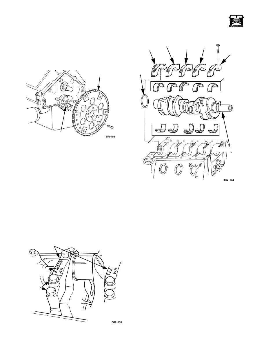
Flywheel Removal
1.
Remove six capscrews and flywheel from crankshaft
(Figure 2-97).
2.
Remove flywheel attaching bolts with impact wrench and
suitable size socket.
3.
Work flywheel off crankshaft flange with rocking motion.
Figure 2-97: Flywheel Removal
Crankshaft and Main Bearings Removal
1.
Inspect main bearing caps. Note if caps have factory I.D.
markings on them. However, if caps do not have factory
marks, it will be necessary to mark each cap with a center
punch, or scriber. Main caps must be reinstalled in same
location and direction, to maintain bore alignment for
crankshaft journals (Figure 2-98).
2.
Remove rear main oil seal.
3.
Remove main bearing cap bolts. Discard bolts.
4.
Tap main bearing caps with rawhide mallet to loosen.
Then lift and remove caps. Keep them in order of removal
(Figure 2-99).
5.
Lift crankshaft out of bearing saddles in block. Place
crankshaft on bench for cleaning and inspection.
6.
Remove main bearing upper halves from block. Keep
bearing halves for inspection and select fit reference.
Figure 2-98: Main Bearing Cap I.D. Marks
Figure 2-99: Crankshaft and Bearing Removal
CYLINDER BLOCK SERVICE
Cleaning
The block can be cleaned with standard parts cleaning equip-
ment. However, if the crankcase and bores are heavily coated
with varnish, gum, carbon, sludge, or rust deposits in the cool-
ant passages, hot tanking will be necessary.
Clean out all oil galleys and water passages with wire brushes
designed for this purpose.
WARNING: The cam bearings (Figure 2-100) must be
replaced if the block is “hot tanked”. The caustic solu-
tion used for this type of cleaning, will etch and weaken
bearing surfaces. The expansion plugs and oil filter
pressure regulating valve must also be removed before
hot tank cleaning.
Coat the block with a light solvent after cleaning to prevent
rust formation. Useful solvents are available from LPS Corp.,
Solder Seal, WD-40 and similar firms.
CRANKSHAFT
FLYWHEEL
FLANGE
MAIN BEARING CAPS
CAP BOLTS
(4 EACH)
CAP LOCATION
AND I.D. MARKS
(REAR MAIN)
CAP
BEARING
BEARING
CRANKSHAFT
REAR
MAIN
OIL
SEAL
NO. 5
NO. 4
CAP
NO. 3
(THRUST)
CAP
NO. 2
CAP
NO.1
(FRONT)
CAP
INSERTS
INSERTS
Нет комментариевНе стесняйтесь поделиться с нами вашим ценным мнением.
Текст