Hummer H1 (2002+). Manual — part 23
____________________________________________________________________
Engine 2-53
®
05745159
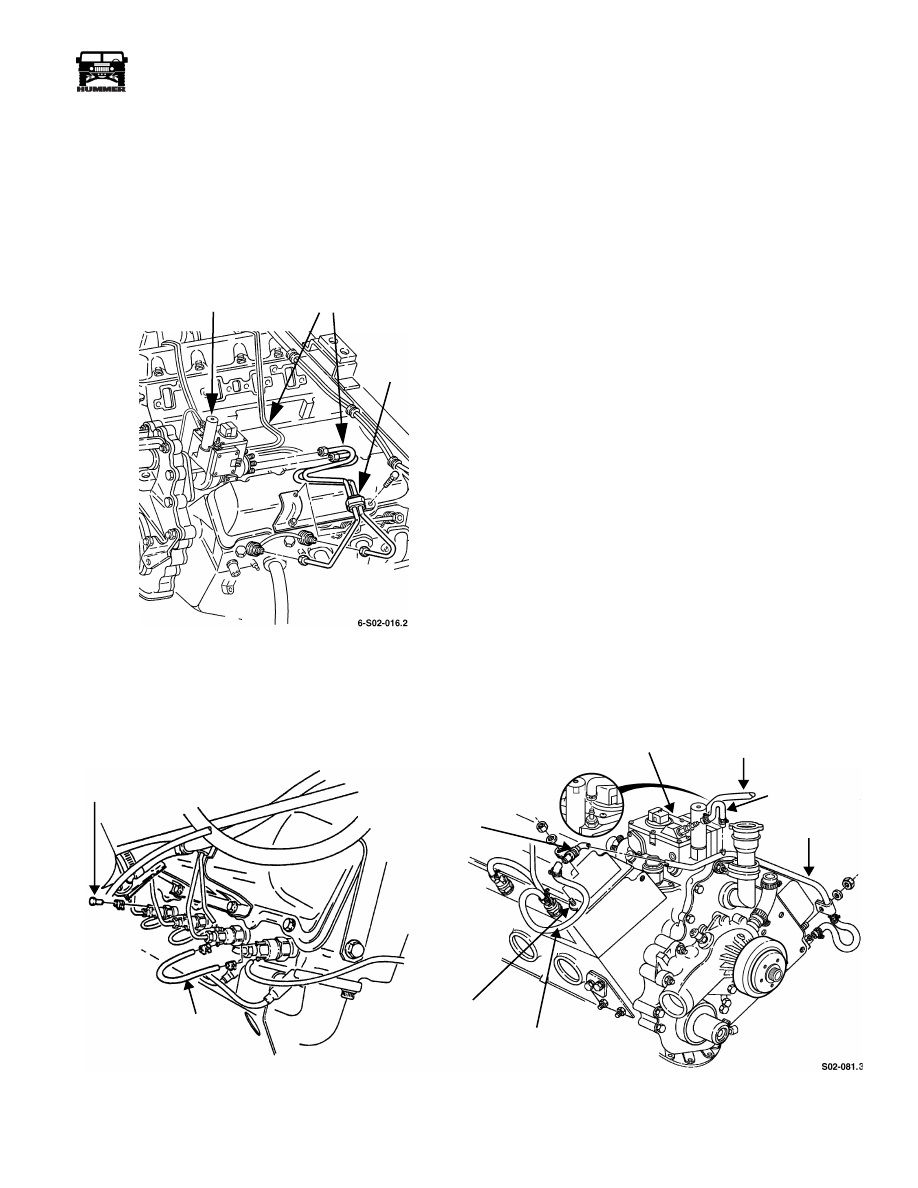
Fuel Injection Line Removal
NOTE:
Mark or tag fuel injection lines for installation refer-
ence.
1.
Disconnect lines at injector nozzles (Figure 2-75).
2.
Remove clamp and boot from lines at injection pump if
equipped.
3.
Disconnect and remove injection lines.
Figure 2-75: Fuel Injection Line Removal
Fuel Supply and Return Line Removal
1.
Loosen clamp and remove fuel supply hose from fuel
injection pump (Figure 2-76).
2.
Loosen clamps and remove fuel return hose from injection
pump and return line (Figure 2-76).
3.
Remove fuel return line clamps at right and left valve
covers.
4.
Loosen clamps securing fuel return hoses to fuel injectors.
5.
Remove fuel return jumper hoses and plugs at fuel
injectors.
Figure 2-76: Fuel Supply and Return Line Routing
INJECTION PUMP
INJECTION LINES
CLAMP
FUEL RETURN
HOSE
VALVE COVER STUD
FUEL RETURN HOSE
FUEL
FUEL INJECTION
PUMP
FUEL RETURN
HOSE CLAMP
PLUG
RETURN LINE
SUPPLY HOSE
FUEL
FUEL
RETURN HOSE
2-54
Engine
_____________________________________________________________________
®
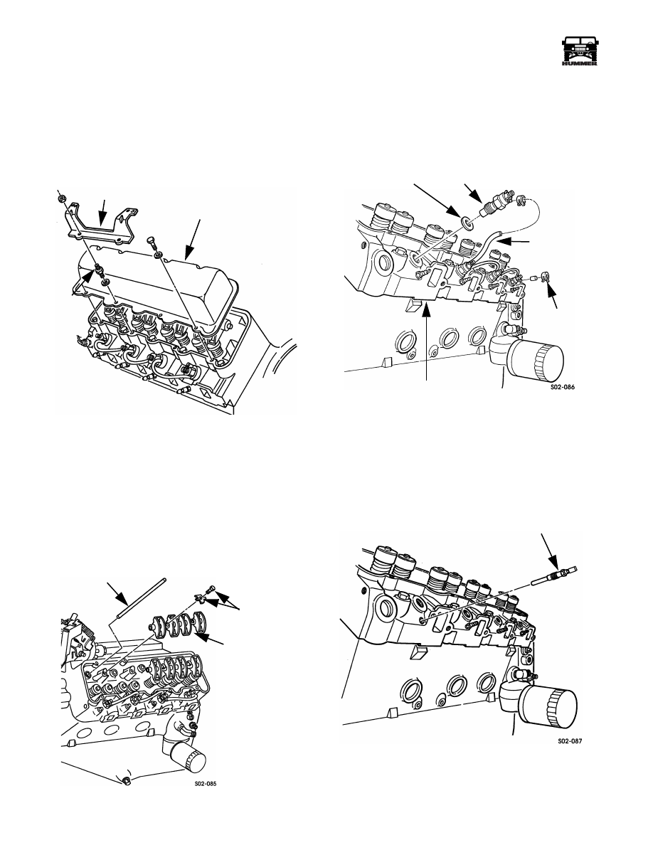
Rocker Arm Cover Removal
1.
Remove injection line support bracket from studs
(Figure 2-77).
2.
Remove cover attaching bolts and studs.
3.
Remove rocker arm cover. Tap cover with rubber mallet
and twist it to remove. Do not pry on cover.
4.
Repeat procedure for opposite cover.
.
Figure 2-77: Rocker Arm Cover Removal
Rocker Arm Shaft and Pushrod Removal
1.
Remove rocker arm retainers and bolts (Figure 2-78).
2.
Mark or tag position of each rocker arm and shaft set
before removal.
3.
Remove rocker arm and shaft sets from cylinder head.
4.
Remove pushrods. Keep pushrods in removal order. Do
not intermix them.
5.
Repeat procedure for opposite rocker sets.
Figure 2-78: Rocker Arm and Shaft Removal
Fuel Injector Removal
1.
Remove fuel return hoses and clamps from injectors
(Figure 2-79).
2.
Remove fuel injectors and gaskets (Figure 2-79).
Figure 2-79: Fuel Injector Removal
Glow Plug Removal
Remove glow plugs from cylinder heads (Figure 2-80). Dis-
card any damaged plugs.
Figure 2-80: Glow Plug Removal
INJECTION LINE SUPPORT BRACKET
ROCKER ARM COVER
STUD
S02-084
PUSHROD
RETAINER
ROCKER ARM
AND SHAFT
SET (2 PER SIDE)
AND BOLT
GASKET
HOSE
CYLINDER HEAD
PLUG
FUEL
RETURN
HOSES
INJECTOR
GLOW PLUG
____________________________________________________________________
Engine 2-55
®
05745159
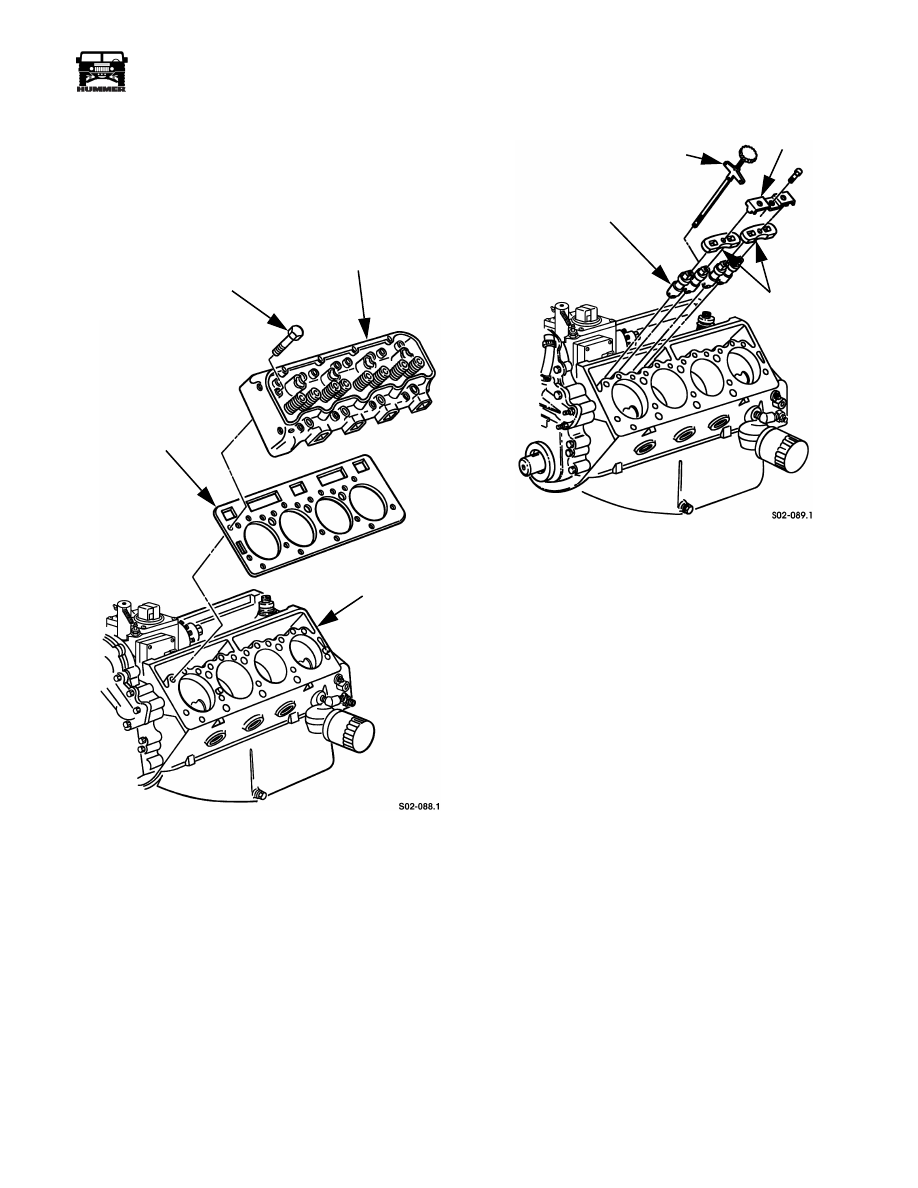
Cylinder Head Removal
1.
Remove cylinder head bolts (Figure 2-81).
2.
Remove cylinder head from block.
3.
Remove cylinder head gasket. Discard gasket afterward.
4.
Repeat procedure for opposite cylinder head.
Figure 2-81: Cylinder Head and Gasket Removal
Valve Lifter Removal
1.
Remove lifter clamp plates from cylinder block
(Figure 2-82).
2.
Remove lifter guide plates from block.
NOTE:
Mark or tag lifters for installation reference. Keep
them in order of removal.
3.
Remove lifters from block with tool J–29834 (Figure 2-82).
Figure 2-82: Valve Lifters
CYLINDER HEAD
GASKET
ENGINE BLOCK
HEAD BOLTS
(17 PER HEAD)
VALVE LIFTER
CLAMP PLATE
GUIDE PLATES
LIFTER REMOVER J–29834

2-56
Engine
_____________________________________________________________________
®
Water Pump/Adapter Plate/Oil Fill Tube
Removal
1.
Remove oil fill tube from adapter plate (Figure 2-83).
Figure 2-83: Oil Fill Tube Removal
2.
Remove water pump and adapter plate from timing gear
cover (Figure 2-84). Note location of attaching studs and
bolts for installation reference.
Figure 2-84: Water Pump and Adapter
Plate Removal
3.
Remove water pump, attaching bolts, and separate pump
from adapter plate (Figure 2-85).
4.
Remove and discard gasket.
Figure 2-85: Water Pump, Adapter Plate,
and Gasket Disassembly
Fuel Injection Pump Removal
1.
Remove electrical connections, fuel inlet and return lines
from pump.
2.
Remove driven gear attaching bolts and remove gear from
fuel injection pump (Figure 2-86).
3.
Remove injection pump attaching nuts and washers from
front cover studs.
4.
Remove fuel injection pump and gasket from timing gear
cover. Discard gasket.
Figure 2-86: Fuel Injection Pump and Driven Gear
Removal
OIL FILL TUBE
ADAPTER PLATE
WATER PUMP
WATER PUMP AND
ADAPTER PLATE ASSEMBLY
WATER PUMP
ADAPTER
PLATE
GASKET
6-S02-187.1
DRIVEN GEAR
FRONT COVER
STUD
GASKET
ELECTRONIC
INJECTION
PUMP
Нет комментариевНе стесняйтесь поделиться с нами вашим ценным мнением.
Текст